Scanning: sequential and interlaced
One of the major drawbacks of CRT displays is flicker. There are two types of flicker that affect a CRT display: inter-field caused by interlacing and the less significant intra-field flicker. Both are caused by electron beam scanning. When the beam scans a line, the phosphor glows and as soon as the beam moves along, the phosphor begins to fade. By the time the beam
reaches the end of a field, the phosphor at the start of the field would have almost completely faded, causing intra-field flicker to occur. Similarly for intra-field flicker, by the time the beam reaches the end of a line, the phosphor at the start would have faded.
In plasma panels, the process of line-by-line scanning is separate from the actual process of light emission. The latter takes place during the sus- tain period exciting and discharging all pixels simultaneously. For this rea- son, flicker disappears completely. It will also be noticed that the ADS plasma addressing technique is sequential and since television broadcast- ing involves interlaced pictures, it is necessary for interlace-to-progressive (I/P) conversion to take place before video data are fed to the video driving board. Table 10.1 shows a comparison between a CRT and a PDP.
Sub-field coding
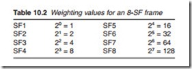
As was stated earlier, the brightness of a pixel cell depends on the number of sustain pulses and therefore the duration of the sustain period. A long sustain period produces more plasma discharges and therefore higher brightness levels and vice versa. A single drive cycle of set–address– sustain produces one level of brightness for all selected cells. To produce different levels of brightness for different cells within a single picture frame, in other words, to produce a greyscale, we need more than one drive cycle in which each drive cycle known as a sub-field (SF) is given a brightness weighting determined by the length of its sustain period. A SF with a short discharge period would result in low brightness and vice versa. If two SFs are used, then 22 = 4 different greyscale levels can be obtained, whereas 6 SFs would result in 26 = 64 different levels. And since each drive cycle or SF requires one bit of video, then the number of bits used to describe the video signal determines the number of SFs. For example the standard eight-bit colour signal would generate eight SFs per frame and with it 28 = 256 greyscale levels.
Table 10.2 shows a binary weighting stretching from lowest order SF1 valued at 1 to the highest order SF7 valued at 128. Figure 10.4 shows the weighting of each SF in terms of its period. Each pixel cell is selected for one, two or more SF to the maximum depending on the required brightness of the cell. For low brightness, the cell is selected and primed for low SFs
while high brightness is achieved by priming the cell for the high order SFs. The total brightness of each pixel cell in a frame is the summation of the brightness produced by each SF. Minimum brightness, i.e. black is obtained when the cell is not selected in any SF and the highest brightness is obtained when a cell is selected for all SFs giving a brightness value of 256.

