IMAGE DISPLAY AND CAPTURE DEVICES
The two essential ends of a video or TV system are the image pick-up device in the camera or telecine, and the display system in the TV set. Many years ago that implied an electron-scan (cathode ray) tube at both ends, and while a thermionic tube is still there in most TV sets and monitors, image scanners are now made of silicon photodiode arrays, while some specialised TVs and monitors use liquid- crystal screens, generally very small ones or very large projection types. In this chapter we shall examine them all, and look briefly at the older technology of TV camera tubes, starting with the most common display system, the thermionic picture tube. Although black- and-white tubes are seldom seen except in miniature form as camcorder viewfinders, an understanding of their operation is an essential stepping-stone to an appreciation of colour picture tubes.
SINGLE GUN TUBE
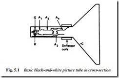
Fig. 5.1 shows the make-up of an electrostatically focused monochrome display tube. Electrons are emitted by a cathode (K) maintained at dull red heat by an internal heating element. The negatively charged electrons are attracted towards the first anode (A1) which is positive with respect to the cathode. The first anode consists
of a skirted disc with a small central hole through which most of the electrons are accelerated. Closely surrounding the cathode is a cup- shaped elecrode called the grid (G) which also has a small central hole. By varying the potential on the grid, typically within the range –25 V to –100 V with respect to the cathode, the density of electrons in the beam can be varied: phosphor brightness depends on beam density, so the instantaneous brightness of the scanning spot can be varied at fast rate by feeding a suitable modulating voltage between cathode and grid; this will normally be the video signal. Provided the scanning spot is in the right place on the screen at the right time a pattern of light and dark picture elements is built up to form a complete picture.
The second and fourth anodes are connected to a conductive layer
(C) on the inside of the bowl of the tube, which itself forms a wall anode. Between anodes 2 and 4 comes the focus electrode A3, a cylindrical anode whose potential (typically variable between +400 V and +800 V d.c. with respect to the cathode) determines the focus- ing point of the electron beam.
Anodes 2 and 4, the wall anode and the inner screen surface are together connected to a source of very high voltage (e.h.t.) which may vary between 5 kV in camera viewfinder tubes and 28 kV in very large-screen colour tubes. This voltage gives the screen-bound electrons tremendous acceleration.
The screen in a monochrome tube is coated with a phosphor, usually composed of a mixture of blue-emitting zinc sulphide and yellow- glowing zinc cadmium sulphide. The combination gives an approximation to white light emission when bombarded with electrons. The phosphor screen is backed by a film of aluminium which has three purposes: It acts as a barrier to heavy ions, prevent- ing them burning the phosphor layer; it reflects phosphor-light forward into the viewing area; and it equalises the electrostatic charge over the entire screen area, preventing spurious local beam-deflection effects.
BEAM DEFLECTION
The square of light on which the picture is built up is called a raster, and to trace it out on the screen of a picture tube the electron beam must be deflected vertically and horizontally. The process is almost invariably a magnetic one in which deflection coils (Fig. 5.2) generate lines of magnetic flux in the tube neck. Note that vertical lines of force are responsible for horizontal deflection and vice versa. The angle through which the scanning beam is turned between opposite corners of the raster (i.e. across the diagonal) is the deflection angle. For medium and large monochrome tubes it is generally 110°. Many colour tubes also have 110° deflection, though 90° deflection is very common, and eases power-consumption and convergence problems. Very small screen tubes have much smaller deflection angles; 50° and even 23° may be encountered.
