Power supply requirements
Different elements of a DVD player require different DC power requirements in terms of voltage and power. Generally, processing and memory chips may require 3.3 V or 5 V, logic devices 5 V, fluorescent indicator tubes on the front panel –10 V, focus and tracking coils -12 V and spindle and sled motors 12 V.
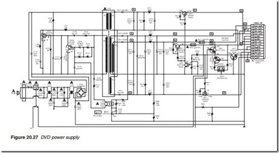
A typical circuit diagram for a DVD player switched mode power sup- ply is shown in Figure 20.27. FET Q101 together with transformer winding W2, C117 and zener Q102 form a self-oscillating circuit running at a rate determined by the time constant R105/C117. The capacitor charges up through R105 and when it reaches a certain voltage, it turns transistor Q101 on which discharges the capacitor turning itself off in the process and so on. Feedback control is provided by the network composed of opto-coupler PC101, transistor Q102 and zener D102. The opto-coupler monitors the voltage level of the 5 V rail. If the 5 V rail goes up, light emit- ted from the photo-diode increases, increasing the current through the photo-transistor, forward biases transistor Q102 and reduces the voltage at its collector. The effect of this is to increase the time it takes for capacitor C117 to charge up thus delaying the switching on of Q101. If the 5 V rail goes down, current through opto-transistor decreases, current through transistor Q102 falls, its collector voltage increases and capacitor C117 charges up faster. The effect of this is to bring forward the switching of Q101 and thus increasing the voltage. On the secondary side of the trans- former, diodes D211 and D511 provide the +10 V and –10 V rails, D311 and D611 provide the Ever 5.5 and 3.8 V rails and transistor Q611 provides switched rail 3.3 V. When the poser supply is in the on mode, Q711 is turned on by a positive voltage from the power control line into its emit- ter, taking its collector voltage to 3 V. This voltage turns FET Q511 on switching the –10 V rail. The 3 V from the collector of Q711 turns transis- tor Q312 on and its collector voltage drops which turn transistor Q611 and FET Q211 on to switch the 3.3 V and the +10 V rails. With the 3.3 V avail- able, Q621 and Q615 are switched on energising the green LED of double LED diode D615. When the power supply is turned into the standby mode, the power control voltage goes down switching the –10 V, +10 V and +3.3 V rails off, turning Q621/Q615 off and lighting the red part of the double LED diode.
Content protection
In the aftermath of the Content Scrambling System (CCS) used in DVD- video having been decrypted and widely distributed over the internet, AACS (Advanced Access Content System) designed a new protection sys- tem which enables authorised use and deters unauthorised copying and re-distribution. The system is based on what is called ‘watermark’ which
the player would detect and enable playback. The absence of the ‘water- mark’ data means the disc is a copy causing the player to refuse to play it. The watermark may be set to a restricted number of copies, normally one after which playback is blocked. In addition, AACS provide guidelines pertaining the outputs over the analogue connections. This sets a flag to restrict the resolution for analogue outputs without the High-Definition Copy Protection (HDCP) to a max of 960 X 540.
