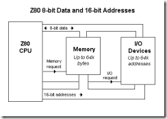
· The Z80 signals can be classified into six groups: address bus, data bus, control signals, external requests, request acknowledge, and power and frequency signals (see section 1 for definitions of these signals).
· The Z80 address bus has 16 unidirectional address lines; they are capable of addressing 64K memory.
· The Z80 data bus has eight bidirectional data lines, and they are used for data transfer.
· The Z80 microprocessor has six general-purpose 8-bit registers IB, C. D. E, H, and L) as a primary set. In addition, it includes the alternate set of these registers that can be used to exchange information with the primary set. The registers Band C, D and E, and Hand L can be combined to perform Some 16-bit operations.
· The ALU section of the Z80 includes accumulator A and the flag register to indicate six different data conditions. It also includes the alternate accumulator A’ and the flag register F’, which can be used to exchange information with A and F, respectively.
· Four flags-Sign, Zero, Carry, and Parity/Overflow-can be used for decision making and tested in conjunction with Jump, Call, and Return instructions. Two flags-Half Carry and Add/Subtract-are used internally for BCD operations and are unavailable for the programmer.
· The Z80 has four 16-bit registers-IX, IY, Sp, and PC-used as memory pointers. Two index registers IX and IY are used to point to any memory location. The stack pointer (SP) is used to specify memory locations in a defined R/W memory segment called the stack. The program counter (PC) is used to sequence the program execution; it points to the next memory address from where the machine code is to be fetched.
· The Z80 is designed to execute 158 instruction types, and each instruction can be divided into a few basic operations called machine cycles.
· The frequently used machine cycles are Opcode Fetch, Memory Read and Write. and I/O Read and Write.
· The Opcode Fetch and Memory Read are operationally similar; the Z80 reads from memory in both machine cycles. However, the Z80 reads opcode during the Opcode Fetch cycle, and it reads 8-bit data during the Memory Read -cycle. In the Memory Write cycle, the Z80 writes data into memory.
· The memory operations are differentiated from I/O operations by two control signals: M͞R͞E͞Q and I͞O͞R͞Q. The signal M͞R͞E͞Q is combined with R͞D and W͞R signals to generate M͞E͞M͞R͞D and M͞E͞M͞W͞R control signals.
· The Z80 performs three basic steps in any of these machine cycles: It places an address on the address bus, sends appropriate control signals, and transfers data via the data bus.
· The 8-bit microprocessors can generally be classified into two categories: One group is register-oriented, and the other is memory-reference-oriented.
