RS:232C Standard
1. What logic convention is followed in RS-232C and indicate the corresponding voltage levels also.
Ans. A negative logic convention is used for such a standard. Logical ‘1’ is represented by a transmitted voltage level in the range of –3V to –15V, while a logical ‘0’ is represented by a transmitted voltage level in the range of +3V to +15V.
2. What is the noise margin of RS-232C and how does it compare with the noise margin of TTL ICs?
Ans. The noise margin of RS-232C is 2V while that for TTL, it is 0.4V only.
The higher noise margin level of RS-232C allows it to pass through more noisy levels
than that permitted for TTL.
3. How RS-232C is interfaced with TTL?
Ans. For such an interface to be done, line drivers and receivers are required. MC 1488 accepts TTL level inputs and provides an output compatible to RS-232C. IC MC 1489 converts RS-232C levels to TTL levels.
4. What is the transition time allowed for RS-232C?
Ans. The transition time (time allowed to switch over from one voltage level to another voltage)
is 4% of one bit time. Thus at 19,200 baud, the transition time is 0.04 × 1/19,200 second= 2.1 mS.
5. What restriction does the transition time impose on the maximum cable length that can be used with RS-232C.
Ans. The transition time puts a limit on the maximum length of cable for information transformation on the RS-232C cable. As cable length increases, so also the capacitive load. This thus impedes transition time. For a baud of 19,200, the maximum cable length becomes around 5 ft.
6. Mention in which case RS-232C is used.
Ans. It is used for serial asynchronous data transmission (a) over telephone lines equipped with modems, (b) in digital systems in which the total cable distance is less than 50 ft.
7. How many pins are there on a RS-232C connector? In how many ways are they divided?
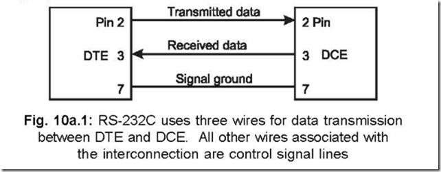
Ans. There are 25 pins on a RS-232C connector. They are divided into two groups—three (3)
wires are used for data transmission/reception purposes. Pin 2 is used for Transmitted Serial Data (TXD), pin 3 for Received Serial Data (RXD) and pin 7 for Signal Ground.
In the other group, twenty-two (22) wires are there which are used for control purposes.
The following figure shows the connections between DTE and DCE for data transmission purposes.
The pin assignments of RS-232C are as here under:
1. Protective (chassis) Ground
2. Transmitted Serial data (TXD)
4. Request to Send (RTS)
5. Clear to Send (CTS)
6. Data Set Ready (DSR)
8. Received Line Signal Detector (DCD)
9. (Used for Data set testing)
10. (Used for Data set testing)
11. Not Used
12. Secondary Received Line Signal detector
13. Secondary Clear to Send
14. Secondary Transmitted Data
15. Transmission Signal Element Timing (DCE Source)
17. Receiver Signal Element Timing
18. Not Used
19. Secondary Request to Send
20. Data Terminal Ready
21. Signal Quality Detector
22. Ring Indicator
23. Data Signal Rate Selector (DTE/DCE Source)
24. Transmit Signal Element Timing (DTE Source)
25. Not Used
8. Indicate to what extent the 50 ft distance limitation of RS-232C can be extended. Ans. It can be extended up to 10,000 ft by using line drivers and twisted pair cables, but at the expense of reduced baud—600 only. Line drivers are signal converters and amplify the digital signals but don’t modulate them into audio signals. This use of line drivers don’t change the transmission frequency also–thus it is referred to as base band signalling.
