IEEE:488 Bus
1. What is a IEEE-488 Bus?
Ans. It is a byte serial, 8-bit parallel, asynchronous type of instrument interface and was introduced by IEEE in 1975. It comes in a standard 24-pin connector.
2. What are the other names by which IEEE-488 bus is known?
Ans. The other names of IEEE-488 bus are GPIB (General Purpose Interface Bus) and the HP (Hewlett-Packard) Interface bus.
3. How the IEEE-488 bus evolved over time?
Ans. The GPIB (General Purpose Interface Bus) was originally developed by Hewlett Packard in 1965—that time called HPIB and was used as a communications standard to connect and control programmable instruments.
IEEE in 1975 introduced a standard, known as, IEEE standard 488-1975 (or IEEE-488) for high speed data communication between instruments manufactured by different companies. The current version of the same standard is referred to as IEEE standard 488.1-1987 and defines the mechanical, electrical and hardware protocol specifications of the communications interface but did not address data formats, message exchange protocols, common configurations commands, device-specific commands, status reporting, error handling, etc.
In 1987, IEEE introduced another standard—called IEEE standard 488.2. This standard is fully compatiable with the earlier standard 488.1 and addresses software protocol issues elaborately.
SCPI (Standard Commands for Programmable Instruments) was introduced in 1990 by several manufacturers and is an improvement over IEEE 488.2 standard. SCPI utilises IEEE 488.2 as a basis and defines a common command set for programmable instruments interconnected with varied hardware links.
4. Write down the advantages of IEEE-488 based measurement system.
Ans. Advantages which are derived by using an IEEE-488 based measurement system are :
z High measurement throughput—ranging from 10 to 100 times faster than conventional manual methods.
z Stored data can be analysed/processed as per the requirements of the particular situation adding functionality to the system.
z Repetitive manual operations can be dispensed with.
z Settings of equipments are highly repeatable—resulting in high consistency in measurements.
z Less skilled workers can handle the system.
z Very high consistency in measurements.
5. What is the maximum data transmission rate of IEEE-488 bus?
Ans. The maximum data transmission rate is 1 mega byte/second. But actual data rate is governed by instruments connected to the bus, as also the distance involved.
6. How many instruments can be connected to such a bus?
Ans. A maximum of 15 instruments can be interconnected to such a bus, but in such a case the total cable length does not exceed 20 m (66 ft).
7. What logic convention is followed and what logic family it is compatiable to? Ans. Signals transmitted over the IEEE-488 bus are TTL logic compatible.
It follows a negative logic convention with logic 0 = TTL high state (≥ 2.0 V), and logic
1 = TTL low state (≤ 0.8 V).
8. Distinguish between the IEEE-488 bus standard and the IEEE-488 bus.
Ans. The IEEE-488 standard is a document that indicates the rules, specifications, timing relationships, physical characteristics, etc. that the instruments connected to the bus must adhere to. This standard includes electrical, mechanical, functional specifications of the instruments interface. The electrical specifications include the current and voltage levels of the transmitted signals, mechanical specifications tell about the number of wires, type of connector, pin designations, etc. The functional specifications indicate the functioning of the different lines, protocols to be obeyed for message transfer, timing relationship between the signal lines and the different kinds of messages that can be carried between different devices.
On the other hand, the IEEE-488 bus is the hardware that is actually used to implement the standard.
9. How many lines comprise the IEEE-488 bus? Discuss.
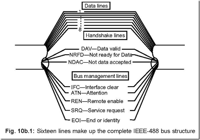
Ans. There are in all sixteen (16) lines that comprise the complete IEEE-488 bus.
These 16 lines are divided into three categories—data lines (8 nos.), handshake lines(3 nos.) and bus management lines (5 nos.). This is shown Fig. 10b.1.
The data lines carry measurement data, program data, addresses, universal commands etc. Handshake signals are required because of asynchronous nature of operation of the bus, whereas the management lines are employed to ensure an orderly flow of data across the bus interface.
10. Is it possible to remove the 20 m restriction while using IEEE-488 bus?
Ans. It is possibly by using ‘bus extenders’. With bus extenders, an IEEE-488 bus system can be extended to several thousand miles. In such a case the instruments are categorised into two groups—remote and local. Functionally there is no difference between a remote instrument and a local instrument connected to the bus—thus the extenders are essentially transparent in nature.
For distances up to 1000 m, several bus extenders are employed by using twin-pair
cables in full duplex form.
If it is beyond 1000 m, then RS-232C cable is employed by serialising the information
available on the 16 lines.
Maximum transmission bit rate is decreased by using bus extenders. This value is kept at 20 K bits/second for transmission up to 1000 m.
Bus extenders support synchronous and asynchronous modems when transmission
involves huge length that includes telephone lines. In such a case, 19.2 K bits/second (synchronous) and 150, 300, 600 or 1200 bits/second (asynchronous) transmission rates are achieved.
11. In how many categories the instruments connected to the IEEE bus can be grouped ? Discuss each such category.
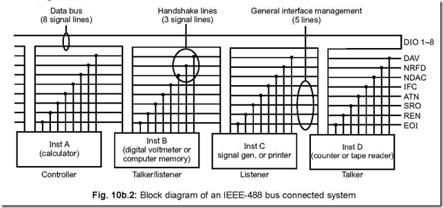
Ans. There are four categories of instruments which are connected to the IEEE bus. These are controllers, talkers, listeners and talkers/listeners. Such a connection is shown in Fig. 10b.2.
Controllers (it may be a computer or a programmable calculator) manage all the operations of the instruments connected to it and direct data flow from one to another.
Listeners are those instruments which receive data. Examples of listeners may be a printer or a recorder.
Talkers send data to listeners. Example of a talker is a digital voltmeter.
Talkers/listeners are able to receive or send data. These may be digital multimeters and network analysers.
12. How many talkers and listeners can be active at any given instant of time?
Ans. At any given instant of time, there can be only one talker (the one which sends data) but there can be more than one listener (the one which receives data).
13. What determines the data transmission rate on the IEEE bus?
Ans. When there are more than one listener who receive data, it is the slowest of them all which determines the data transmission rate.
14. What makes a listener or a talker to become ‘active’?
Ans. Each of the talkers or listeners has a unique address associated with it. A talker or a listener can become active by invoking the corresponding unique address.
15. Who controls the three handshake lines?
Ans. The three handshake lines are DAV (data valid), NRFD (not ready for data) and NDAC (Not data accepted).
It is the active talker and listeners who control the three handshake signals. The particular talker and listener are made ‘active’ by the controller, after which the controller has no part to play until data transfer is over.
DAV line is controlled by the active talker which places valid data on the data lines. The NRFD and NDAC lines are controlled by the active listeners to indicate their preparedness to receive data and acceptance of data respectively.
16. Discuss the function of the GPIB controller.
Ans. At any given point of time, only one device can act as an active controller. Another device may seek the control and can act as a controller once the active controller passes control to it.
For proper communication, each device is assigned a unique GPIB address—called
primary address of the device. The primary address ranges from 0 to 30, although a maximum of 15 devices can be connected via the bus. Assignment of a device address is by DIP switches, jumpers, etc.
Usually, a PC acts as a controller—a GPIB control card is thus installed in the PC then. This controller designates which device will be talker and which device(s) would be listener(s). The controller, during initialisation, assigns the device addresses.
A new GPIB protocol—called HSS 488, introduced by National Instruments, allows data transfer rates up to 8 MB/second.
17. How the devices are configured via GPIB?
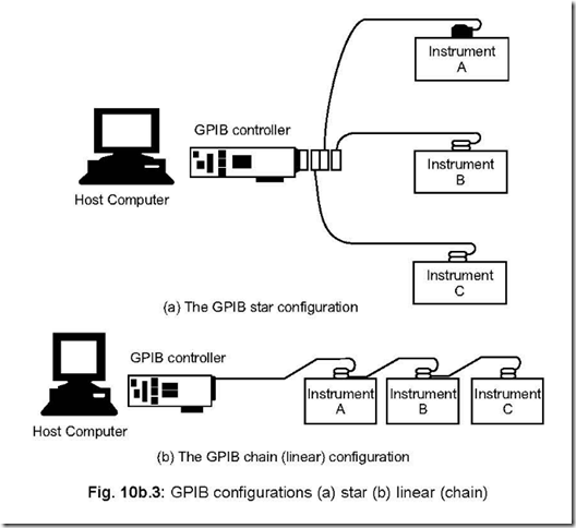
Ans. The devices, connected via the GPIB bus, are configured in one of the three ways :
z Star
z linear (chain)
z a combination of the two.
Figure 10b.3. shows the star and linear configurations. For star connection, all connectors are connected to the same port of the controller. The connected devices must be physically close to the other controller because of length limitation of each cable imposed by the standard.
In linear or chain configuration, each device, including the controller, is connected with the next one on the chain. The controller can be placed anywhere in the chain. In this, the software needs reconfiguring in case a device (including its cable) is removed.
18. Draw the IEEE-488 bus connector and state the functions of each pin.
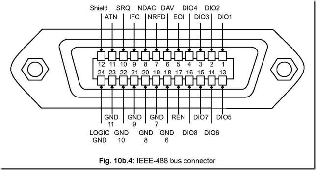
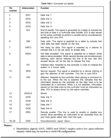
Ans. The IEEE-488 bus that connects the various instruments and controllers are connected via a 24 pin IEEE-488 bus connector. The connector is a 24 pin type, shown in figure 10b.4.
The pin numbers, their abbreviations and corresponding functions are tabulated in Table 10b.1.
Notes :
1. Handshake signals (DAV, NRFD and NDAC) employ active low open-collector outputs which may be used in a wired-OR configuration.
2. All remaining signals are fully TTL compatible and are active low (asserted low).
3. Pins 18 to 23 are intended for use with twisted pair grounds for the control signals
(DAV, NRFD, etc.) that appear on pins 6 to 11 on the other side of the connector).
19. How the request for service is taken care of by the system?
Ans. It is the SRQ (Service request) line which gets asserted when a device requests for service from the controller. The SRQ line is a wire-ORed, i.e., the device service lines are ORed together and connected to the SRQ pin of the bus connector. The device which has interrupted is identified by the controller by polling schemes—either serial or parallel.
For serial polling, each device places a status byte on the bus with DIO7 set if the device in question is requesting service, otherwise it will be in reset condition. Now the active controller polls each device to get to know the particular device which has generated the service request. The remaining 7 bits of the status byte represent the status of the particular device.
For parallel polling an individual data line is asserted by each device. Thus it is very easy for the controller to determine/identify the device which has drawn the attention of the controller.
20. Mention the services provided by GPIB bus. Ans. Operations available on the GPIB bus include:
z to support request of service from a device
z clearing devices selectively or universally
z device dependent functions.
When a device seeks to get the service from the controller, it asserts for the same
via the SRQ line. The controller, on its part, determines the particular device via either
serial or else parallel polling scheme.
In the serial polling scheme, the controller, via a command, enquires about the
status of each device one often another. This scheme is a slow one in which the last
device which is queried, has the least priority.
In the parallel polling scheme, the command issued by the controller, polls all the
devices connected to the system simultaneously. It is a fast process but a complicated one.
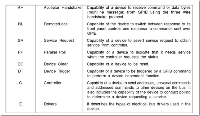
21. Show the interface capabilities of GPIB, their functions and also their descriptions.
Ans. The interface capabilities of GPIB, their symbols and also their functions are tabulated below, vide Table 10b.2.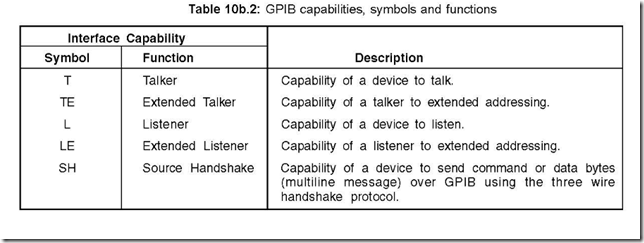
22. Discuss the GPIB commands.
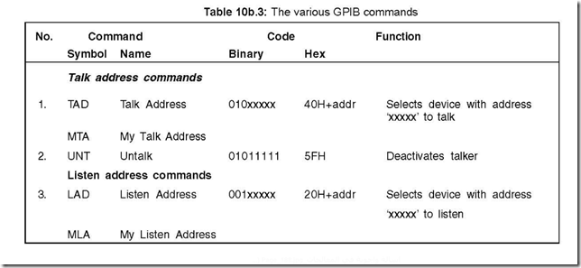
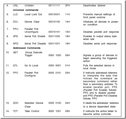
Ans. The GPIB commands are classified into several groups.
z Talk address commands
z Listen address commands
z Universal commands z Addressed commands z Secondary commands
The first four fall under the purview of Primary commands. All the functions under these four commands are shown in Table 10b.3.
Secondary commands, when used, are always used in conjunction with primary commands. When the number of devices to be addressed exceeds 30, an extra byte is needed to specify these devices for their talk/listen functions. This extra byte is the secondary address command byte. This is sent immediately after talk/listen address command. The secondary address command is 60H+address. The maximum address limit is 961 by this method. This type of addressing is called extended addressing and the devices are called extended talkers/listeners.
23. Discuss the End of Interface Message/Data.
Ans. There are three ways to achieve the above. These are:
z EOS (End of String)
z EOI (End of Identity) and
z Count Method
Talkers/listeners must be configured to use one of the three methods to achieve the above—the manual must be consulted to configure in one of the three methods.
EOS uses an EOS character like carriage return (OD H) or a new line (OA H). A talker places the EOS character at the end of the data string. The listeners read the character bytes until it comes across the EOS character—then the listener understands that no more data bytes are there and the listener terminates the read operation.
EOI method uses the EOI signal existing as the GPIB signal line to terminate the message. The talker sets the EOI line status high at the end of message transmission. The listener detects the active EOI signal (high) and understands that no more data bytes are there from the talker. The listener then terminates the read operations.
In the third i.e., count method, the device receives the information about the total number of bytes to be read. Thus in this method the talker can send a specified number of bytes on the bus.
In some cases more than one combination is used for termination of message. In such a case, the termination is effected on the basis of logical ORing of the methods employed.
24. How GPIB programming is done?
Ans. A cluster of devices/instruments connected via the GPIB bus share data/information between them. The GPIB bus helps establish this sharing of information, perform management and bus control operations, sending device dependent/independent commands, sending data either in string or binary format.
GPIB programming is a must to achieve all of the above—the programming can be done either in low level or high level versions.
In the low level programming, the GPIB controller sends the commands which are necessary for bus management and addressing in sequence the devices which are connected via the bus. In high level programming, the overhead due to codes required for programming is drastically reduced. In this, a programmer needs to know lesser information about GPIB protocol and bus management operations.
High level language involves four methods—DOS device driver, onboard EPROM, program language interface and Windows DLL.
25. What are the jobs performed by the five management lines?
Ans. The five management lines are : IFC (Interface Clear), ATN (Attention), REN (Remote Enable), SRR (Service request) and EOI (End or Identity).
The jobs performed by the IFC line are:
(a) It is used to initialize the bus and clear it if something goes wrong.
(b) It helps return the bus in a quiescent or known state. This is done by the controller
to override all current activities and abort all present data transfer processes.
The jobs performed by the ATN line are:
(a) How many data lines are being processed at any given instant of time.
(b) When ATN line is true, data lines contain either addresses or universal commands.
In such a case only the controller talks.
(c) When ATN line is false, the addressed devices can use the data line. In such a case,
data that are transmitted are device dependent.
The jobs performed by the REN line are:
(a) When REN is active, it allows the bus to control a device.
The jobs performed by the SRQ line are:
(a) With its help, a device can seek the attention of the controller. Such a case arises when the device has data to send (the device is a talker) or the device is to receive data (the device is a listener).
(b) Such a request (and not a command) can be rejected by the controller if it does not have any time to service the request.
The jobs performed by the EOI line are:
(a) It can be used by the controller as a polling line.
(b) It can be asserted by the active talker to designate the end of a message.
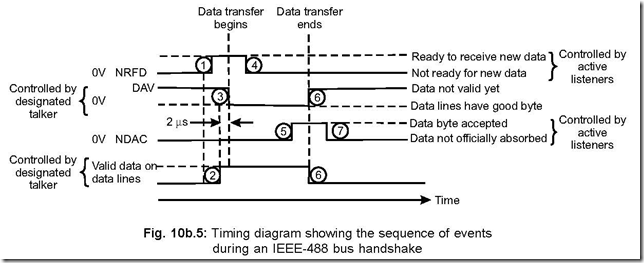
26. Draw and explain the timing diagram showing the sequence for data transfer to take place.
Ans. The following figure shows how data transfer is effected taking the help of handshake signals.
Sequence of events that follow on the time scale (1) ⇒ (2) ⇒ (3) ⇒ (4) ⇒ (5) ⇒
(6) ⇒ (7).
The sequence of events that take place can be explained as follows:
1. Listener(s) which will accept data indicate their readiness with regard to their data acceptance via NRFD (Not Ready For Data) line. If NRFD is low, it indicates that the listener(s) is/are not ready. Only when all the listeners are ready, the NRFD line will go high.
2. The designated talker then drives all the eight input/output lines, causing valid data to be placed on them.
3. The active talker pulls the DAV (data valid) line to zero volts 2 µS after serial number (2). This 2 µS is required for the data to settle to their respective values on the data lines.
4. The listeners now pull the NRFD line to zero, which prevents any additional data transfer from being initiated. The listeners then accept data at their individual rates.
5. When all the listeners have accepted data, the NDAC line goes high.
6. When the active talker sees that NDAC line has become high, it stops driving the line and also it releases the DAV line. The talker is now in a position to put the next data on the data bus.
7. NDAC line is pulled down to zero volt by the listeners and the data is then taken ‘away’ by the listeners.
Thus the sequence of operations that take place on the time scale are (1) ⇒ (2)
