Test 12. Interfacing a PIC microcontroller to an LCD Hitachi Display.
We used an LCD 2x 16 HMC 16225 S-PY alphanumeric display module that is HD44780 compatible. Display has two lines, 16 characters each.
Low nibble of the port B: lines PORTB <3:0> communicate with DB7(pin 14) : DB4 (pin 11) of the LCD Display. LCD control signals E (Enable) and RS (Register Select) are connected to the RB4 and RB5 microcontroller PORTB lines respectively.
In 4-bit mode, two transfers per character / command are required. Half of the byte is sent in one operation, upper nibble first.
LCD’s (drivers) are slow devices when compared to microcontrollers. Care must be taken from having communication occur too quickly. The software will need to control communicaton speed and timing to ensure the slow LCD and fast micro- controller can stay synchronized.
B. Borowik, Interfacing PIC Microcontrollers to Peripherial Devices, Intelligent Systems, 56
Control and Automation: Science and Engineering 49, DOI 10.1007/978-94-007-1119-8_12,
© Springer Science+Business Media B.V. 2011
When we start to communicate with the LCD module, we follow a standard LCD initialization sequence as recommended by the manufacturer. The initialization sequence must be timed precisely (see the HD44780 instruction set for details) and cannot be initiated before at least 30 ms have been granted to the LCD module to proceed with its own internal initialization (power on reset) sequence.
When the module powers up, the default data transfer mode is 8-bit. The initializa- tion sequence only requires commands that are 4-bit in length. The last initialization command needs to specify the data transfer width (4-or 8-bit). Then a delay of 4.6 ms must be executed before the LCD module can be initialized.
The LCD controller needs 40 to 120 microseconds (uS) for writing and reading. Other operations can take up to 5 mS. During that time, the microcontroller can not access the LCD, so a program needs to know when the LCD is busy. We can solve this in two ways.
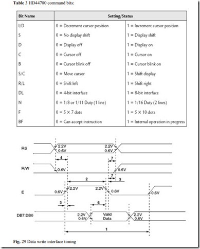
One way is to check the LCD status register BUSY bit (BF flag) found on data line D7 (LCD pin 14). When it is low, data is written to LCD, the LCD is ready for next operation. When it is high, operation is in progress and we have to wait. On the testing board MICROCON4, R/W line is grounded and always in low therefore reaing from the LCD module status-register is disabled.
The other way to ensure, LCD is not busy, is to introduce a delays in the program. The delays have to be long enough for the LCD to finish the operation in process. The practice shows, that following delays are needed for LCD operations:
When the LCD is initialized, it is ready to continue receiving data or instructions. If it receives a character, it will write it on the display and move the cursor one space to the right. The Cursor marks the next location where a character will be written. When we want to write a string of characters, first we need to set up the starting address, and then send one character at a time.
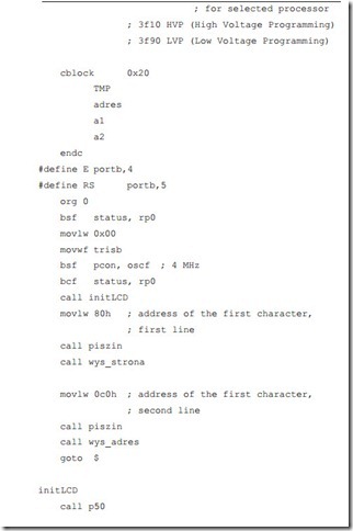
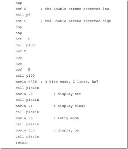
Before we can use initLCD, the delay procedures p50 (50 ms delay), p5 (5 ms delay) and p100 (100 us delay) must be defined. Also initLCD uses procedure for sending command to LCD: piszin. This procedure will be described later.
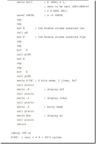
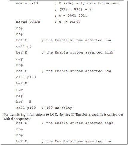
At the beginning initLCD procedure manually sends 3 times to LCD the value of 3 contained in the lower nibble of port B. Transfer is through raising and lowering the Enable strobe line.:
initLCD
call p50 ; 50 ms delay
Raising and lowering voltage on the line is called strobe. It activates information transfer. Both the data and control lines are on the same port: port B, therefore care has to be taken, that line E is on the low state, otherwise any unwanted in- formation can be sent to LCD. Usualy most of operation is performed on the working register W and, when the byte is ready to sent, it is splited into 2 nibbles, they are one after another moved to low 4 lines of port B and then the strobe sig- nal is generated.
Next initialization sequence: sending commands: 0x28, 0x08, 0x01, 0x06 and 0x0c is implemented with the transfer procedure piszin, as shown below:
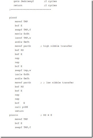
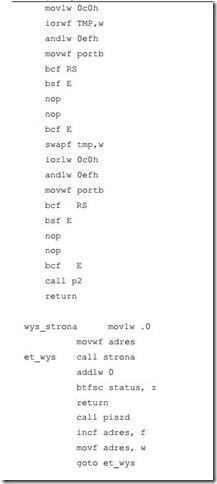
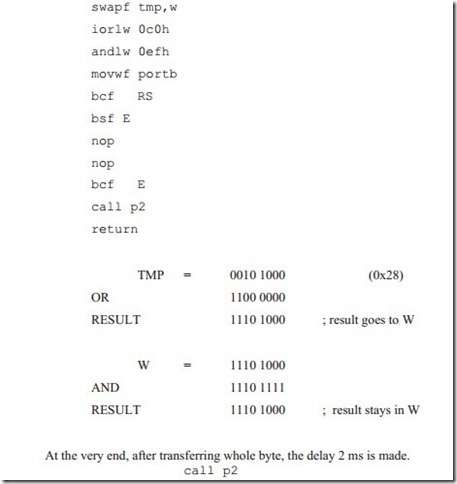
Executing each command requires at least 1.6 ms. We provide after each transfer the 2 ms delay. The respective call (call p2) is included in the piszin procedure. The description of the piszin procedure, for transferring commands to LCD:
Before calling piszin, the byte to be sent is loaded to the working register W.
The LCD controller contains two separately addressable 8-bit registers: one for ASCII data and one for commands. LCD has an address line, RS, for the register selection. Its settings have the following meaning:
Register Select Control RS:
The byte to be sent has two nibbles. We have to send higher nibble first. Send operation is made on the lower 4 lines of PORTB. Therefore the byte has to be swaped and its higher part is on the lower position. Next we have to clear bits 4th and 5th, so that lines RB4 (E signal) and RB5 (RS line) of port B will be cleared. We do this with or and and operations (commands: iorwf and andlw).
Example:
If we are to send command byte 0x28, we first load the value to variable register TMP. After swapf operation, TMP register will contain 0x82, binary b’1000 0010’. We have to make sure, that line 4 (Enable) is zero. Therefore we perform inclusive or operation of this value with the mask b’1100 0000’, so that bits 6 and 7 are set, and lower bits are preserved without changes. Then we make and opera- tion with the mask: b’1110 1111’ and bit 4th is cleared. This looks as follows:
Now it is time to send next nibble. TMP register is swapped again. After iorlw and andlw operations with tha same masks result is moved to PORTB:
After initialising LCD we have to address upper or lower line of LCD. LCD controller recognizes address command, if the MSB is set. Therefore the addres of the beginning of the upper LCD line would be not 0x00, but 0x80, binary 1 0 0 0 0 0 0 0. For the lower line addres starts with 0x40. After seting the MSB it would be in hex: 0xC0, binary 1100 0000.
Because those addresses are commands, RS line has to be held low.

![]() We like to display in the upper line the string : borowik.pl. We generate this string and store in the memory with the procedure wys_strona.
We like to display in the upper line the string : borowik.pl. We generate this string and store in the memory with the procedure wys_strona.
In the above procedures we form a lookup table. First we load 0 to the working register W and to the variable address. Then we call the one line procedure strona. Contents of W is table offset value. It is added to the Program Counter. Upon return W contains one by one all characters from the string. String is null terminated and after each return (retlw) contents of W is checked, if it is zero. If zero, procedure wys_strona ends. If not zero, character is sent to LCD in the pro- cedure piszd, variable address determining table offset is incremented, is moved to W and again is called procedure strona.
dt directive (Define Table) generates a series of RETLW instructions, one in- struction for each character in the string. Each character in a string is stored in its own RETLW instruction. This directive is used when generating a table of data for the PIC12/16 device family. If we were using a PIC18 device, it is recommended that we use the table read/write (TBLRD/TBLWT) features instead. Let us again consider one line procedure strona
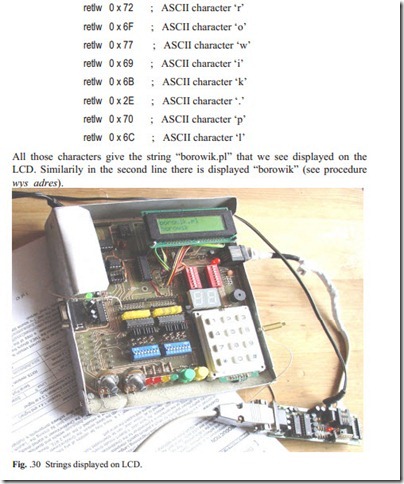
All those characters give the string “borowik.pl” that we see displayed on the LCD. Similarily in the second line there is displayed “borowik” (see procedure wys_adres).
Procedure piszin, described earlier sends commands to the LCD controller. Procedure piszd for sending data (ASCII characters) to LCD is similar. The only differ- ence is, that the RS (Register Select) line must be set high.


