Test 14. Dual RS232 software interface for PC and PIC microcontroller
In many PICMicros a built in serial interface, known as USART for “Universal
Synchronous/Asynchronous Receiver/Transmitter” is available. This hardware al- lows data to be received and sent without any software involvement. To send data, the USART simply shifts the data out (low byte first) to the TX I/O pin.
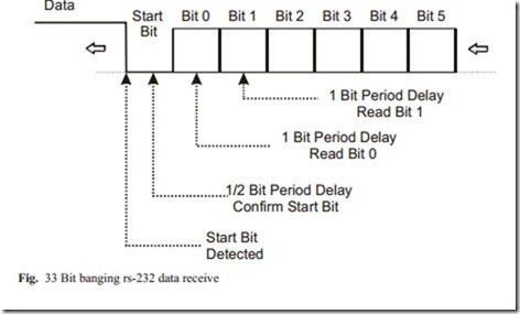
To receive data, the USART works by polling (sampling) the serial data input line at sixteen times the data rate. When a “low” is detected, the hardware waits 8 poll- ing cycles to check to see if the line is still low half a bit period later. If it is, then a bit is read every sixteen polling clocks until the whole byte has been read in. At the end of the byte, the Stop bit is checked to be high. If the byte is received with- out any problems, a byte received flag is set.
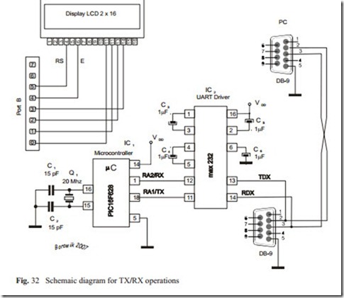
The software presented in our test provides similar serial interface functions while using not USART module, but general purpose I/O pins. This type of interfacing is known as “Bit Banging”. On the testing board serial input is connected to mi- crocontroller pin 1 (PIC16F628 RA2). Serial output is connected to microcontrol- ler pin (RA1). The Maxim “Max232” chip was used because it usesa single +5 Volt power supply. The schematic diagram is presented below.
Program description
We use Bit-Banging method to emulate serial port. In this method we manage all synchronization and timing signals and we have to ensure proper setup and times for reading and writing data to the ports.
Bits are transfered in „8-N-1” format which means that eight data bits are sent with a single (low) Start Bit and high Stop Bit to make up a data packet. “8-N-1 is a simple and convenient protocol. The packet ends with a “1” being sent as a Stop Bit, to allow the “0” Start Bit to be easily recognised. In the idle state the line is on high. N letter means that no parity checking is performed.
Each bit is transmitted for a set period of time, the reciprocal of which is the “data rate”. Common data rates are 300, 1200, 2400, 9600, 19200 bps. As equipment
got faster, the data rates became multiples of these speeds. For the rate 9600 bps the bit time is:
1/9 600 = 104.1 μs
In our experiment we use the slow transmission: 110 bps. For this rate the bit time is:
1/110 = 9.09 ms
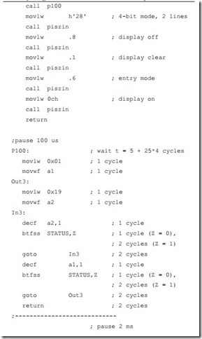
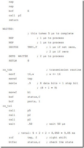
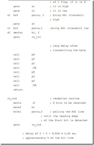
The signal for each bit, whether 1 or 0, has to stay on the transmit line over the time of app. 9.09 ms. We achieve this delay adding up: 2ms+ 2ms + 5ms + 50 μs
= 9.05 ms. The least significant bit is sent first, immediately after the start bit that is always low (0).
The start bit is an initial zero bit and the stop bit is a trailing one bit. The binary code b’01000001’ (code of the character ‘A’) is actually transmitted as follows: first the start bit 0, then 8 bits in reversed order and the stop bit high: : -> 0,0,1,0,1,0,0,1,0,1 with the start and stop bits added and the least significant bit sent first. The signal line idles at a ‘1’ (high) normally so the start bit is a change from idle to a 0 and the stop it continues at a one.
It is good custom to end the tranmission with 2 stop bits (8N2), while perform re- ception with the format 8N1. It provides some synchronization between TX and RX, assuming approximations in the delay procedures. Also between bytes we en- tered longer delays for the demo purposes.
To receive data, the input line is continuously polled. When the leading edge of the start bit is detected, a half bit delay is made:
9,09/2 = 4,5 ms.
and the input line is polled again 8 times with time intervals 9.09 ms after each poll. At the end of the packet the Stop Bit is checked and the routine returns to its caller with the received byte.
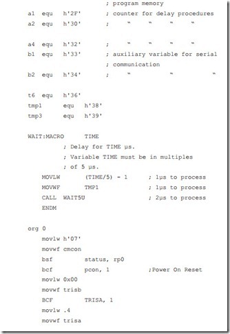
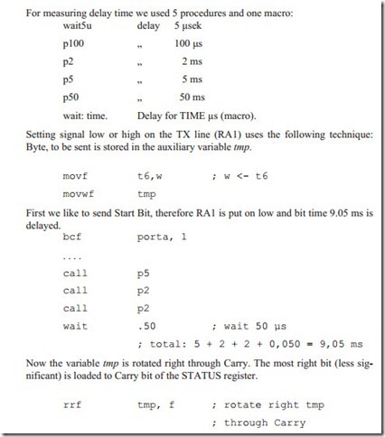
For measuring delay time we used 5 procedures and one macro:
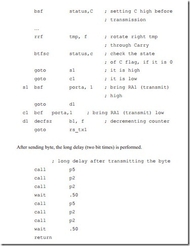
Then the state of C flag is checked. If it is high, the line RA1 is set high too. If C flag is low, RA1 is brought to low. Finaly the delay 9.05 ms is performed. This procedure is repeated 9 times (counter b1), so, that the whole byte and stop bit are outputed. Last bit sent is ‘1’, because before transmission the C Flag was set.
Receiving data is carried out in the similar manner (procedure rs_rxd).
The state if RA2 line is checked. If it is high, Carry flag is set high. If RA2 is low, the Carry Flag is brought low too. Then the auxiliary variable tmp is rotated right through Carry, loading with received bits.
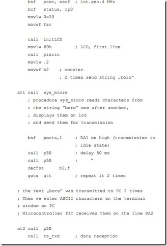
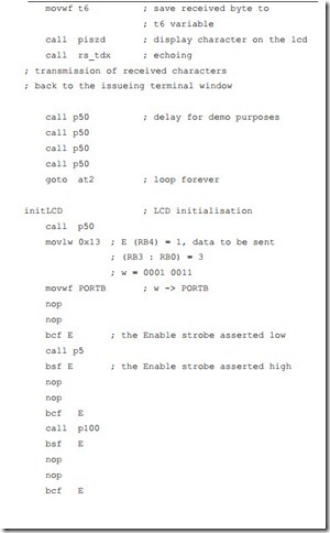
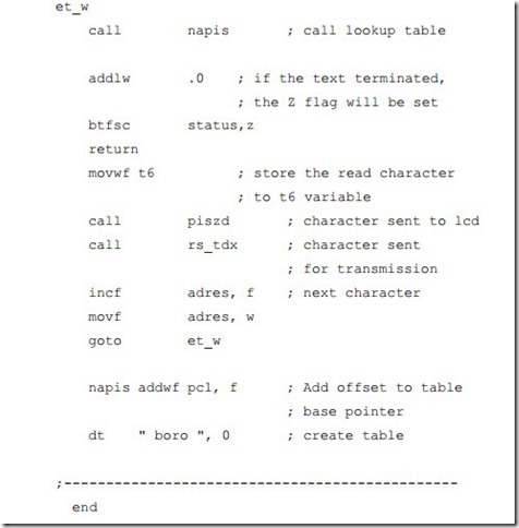
Above presented application makes first reading the text ‘boro from the lookup table. Text is 2 times written to lcd and transmitted to terminal window on PC. It can be Microsoft HyperTerminal application, but we would recommend application Tera Term Pro because of its simplicity.
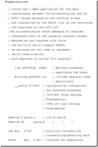
After displaying on the terminal window the text: boro boro, the transmission from the PIC microcontroller is terminated and the microcontroller waits for data from PC. ASCII values entered on the terminal window are transmitted by the RS232 link to the controller and displayed on the LCD. The microcontroller sends feedback of received characters back to the issueing terminal window.
