8289 Bus Arbiter
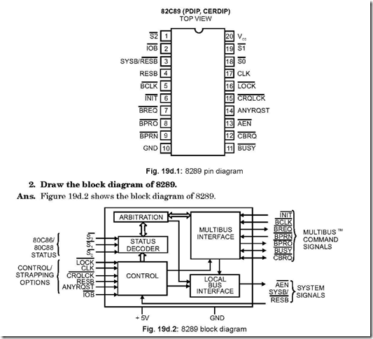
1. Draw the pin connection diagram of 8289.
Ans. The following is the connection diagram of 8289.
3. Explain how 8289 bus arbiter operates in a multi-master system.
Ans. In MAX mode 8086 processor is interfaced with 8289 bus arbiter, along with bus controller IC 8288 in a multi-master system bus configuration. When the processor does not use the system buses, bus arbiter forces the bus driver output in the high impedance state. The bus arbiter allows the bus controller, the data transreceivers and the address latches to access the system bus.
On a multi-master system bus, the bus arbiter is responsible for avoiding the bus contention between bus masters.
4. How the arbitration between bus masters works?
Ans. The bus is transferred to a higher priority master when the lower priority master completes its task. Lower priority masters get the bus when a higher priority one does not seek to access the bus, although with the help of ANYRQST input, the bus arbiter will allow to surrender the bus to a lower priority master from a higher one. The bus arbiter maintains the bus and is forced off the bus only under HALT instruction.
5. Discuss LOCK and CRQLCK signals.
Ans. Both are active low input signals, the second one standing for Common Request Lock.
A processor generated active low signal on the LOCK output pin is connected to
LOCK input pin of 8289, and prevents the arbiter from surrendering the multi-master system bus to any other bus arbiter, regardless of its priority.
CRQLOCK: An active low on this input pin prevents the arbiter from surrendering the multi-master system bus to any other bus arbiter IC after being requested through CBRQ input pin.
6. Discuss AEN and INIT pins of 8289.
Ans. Both are active low signals, with the former being an output signal and the latter an input signal.
A high on AEN signal puts the output drivers of 8288 bus controller, address latches and the 8284 clock generator into high impedance state.
An active signal (= 0) on INIT input resets all bus arbiters on the multi-master system bus. After initialisation is over, no arbiter can use the said bus.
7. Discuss RESB and SYSB/ RESB pins of 8289.
Ans. Both are input pins for 8289 bus arbiter. RESB and SYSB stand for Resident Bus and System Bus respectively. When RESB is high, the multi-master system bus is requested
or surrendered which is a function of SYSB/ RESB input. When RESB is put to low, SYSB/ RESB input is ignored.
Again, the arbiter requests the multi-master system bus in the System/Resident Mode
when SYSB/ RESB is high and allows the bus to be surrendered when this pin is low.
8. Explain BREQ and BPRO pins.
Ans. Both are active low output pins. The first one stands for Bus Request while the second one stands for Bus Priority Out. BREQ is used in the parallel priority resolving scheme which a particular arbiter activates to request the use of muti-master system bus. BPRO is used in the serial priority resolving scheme and it is daisy-chained to BPRN of the just next lower priority arbiter.
9. Explain BPRN pin.
Ans. It is an active low input and stands for Bus Priority In. When a low is returned to the arbiter, it instructs the same that it may acquire the multi-master system bus on the falling edge of BCLK . The active condition of BPRN indicates that it is the highest priority arbiter presently on the bus. If an arbiter loses its BPRN active signal, it means
that it has lost its bus priority to a higher priority arbiter.
10. Explain BUSY pin.
Ans. It is an active low input-output pin. With the availability of multi-master system bus, the highest priority arbiter seizes the bus, as determined by the status of BPRN input. This thus keeps the other arbiters off the bus. When the particular arbiter has completed its job, it releases the BUSY signal, thereby allowing the next highest arbiter to seize the bus.
11. Explain ANYRQST and CBRQ pins.
Ans. ANYRQST stands for Any Request—it is an active high input pin. CBRQ is, on the other hand, an input/output active low pin and stands for Common Bus Request.
An active signal on ANYRQST would enable the multi-master system bus to be
handed over to an arbiter—even if it has lower priority. When acting as an input, an active condition on CBRQ tells the arbiter of the presence of other lower priority arbiters in the multi-master system bus.
The CBRQ pins of the particular arbiters which would surrender to the multi-master system bus are connected together.
The running arbiter would not pull the CBRQ line low—rather it is done by another arbiter seeking the services which pulls the CBRQ line low. The presently run arbiter then drops its BREQ signal and surrenders the bus, when proper surrender conditions
exist. If CBRQ and ANYRQST are put into active conditions, the multi-master system bus would be surrendered after each transfer cycle.
12. Mention the methods of resolving priority amongst bus masters.
Ans. On a multi-master system bus, there may be several bus masters. The particular bus master which is going to gain control of multi-master system bus is determined by employing bus arbiters. Several techniques are there to resolve this priority amongst bus masters. They are:
z Parallel Priority Resolving Technique.
z Serial Priority Resolving Technique.
z Rotating Priority Resolving Technique.
13. Discuss the Parallel Priority Resolving Technique.
Ans. The technique of resolving priority in this scheme is shown in Fig. 19d.3. Four arbiters have been shown each of whose BREQ (Bus Request) output line is entered into apriority encoder and then to a decoder. The BPRN (Bus Priority In) output lines of the encoder are returned—one each to each of the arbiters.
But corresponding to the highest priority active BREQ , an active BPRN is obtained, which activates the respective bus arbiter, neglecting the lower priority BREQ’s .
Thus the bus master corresponding to this bus arbiter will identify itself with the multi- system bus master or would wait until the present bus transaction is complete.
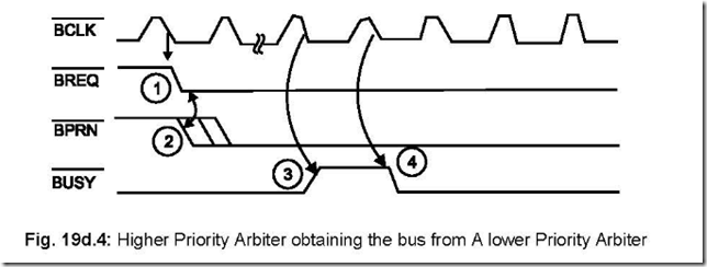
Fig. 19d.4 shows the waveform timing diagrams of BREQ, BPRN and BUSY signals, which are synchronised with BLCK . The explanation of the waveform timing diagram is as follows. When the bus cycles are running, the BREQ line goes low [ 1 ]. There can be more than one BREQ line going low during this time. But the 74HC138 3 to 8 decoder would output a low on that particular BPRN [ 2 ] which corresponds to the
![]()
![]() thereby pulling it off from the multi-master system bus. In the next BLCK cycle, the arbiter which just had the right to use the system bus, pulls its own BUSY line low,
thereby pulling it off from the multi-master system bus. In the next BLCK cycle, the arbiter which just had the right to use the system bus, pulls its own BUSY line low,
thereby making it active and at the same time forcing other arbiters off the bus.
14. Discuss the Serial Priority Resolving Technique.
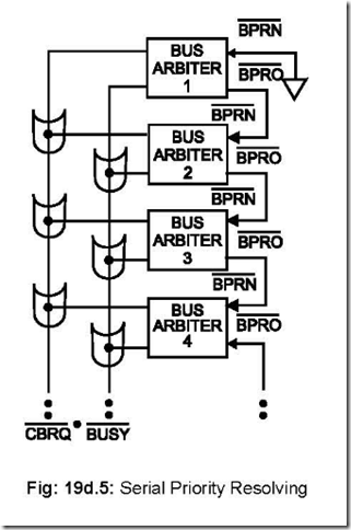
Ans. Figure 19d.5 shows the technique employed in this scheme. This scheme does away with the hardware combination of encoder-decoder logic as employed in Parallel Priority
![]() Scheme. Instead, the higher priority bus arbiter’s BPRO (Bus Priority Out) is fed to the BPRN (Bus Priority In) of the just next lower priority one.
Scheme. Instead, the higher priority bus arbiter’s BPRO (Bus Priority Out) is fed to the BPRN (Bus Priority In) of the just next lower priority one.
15. Discuss Rotating Priority Resolving Technique.
Ans. In this scheme, the priority, to get the right to use the multi-master system bus, is dynamically reassigned. The circuitry is so designed that each of the requesting arbiters gets an equal chance to use the multi-master system bus.
16. Compare the three types of Priority Resolving Techniques.
Ans. In the serial priority scheme, the number of arbiters that may be daisy-chained together
![]() is a function of BLCK , as well as the propagation delay that exists from one arbiter to the next one. With a 10 MHz frequency of operation, a maximum of 3 arbiters can be so connected.
is a function of BLCK , as well as the propagation delay that exists from one arbiter to the next one. With a 10 MHz frequency of operation, a maximum of 3 arbiters can be so connected.
The rotating priority resolving technique employs a considerable amount of external
logic for its implementation. The parallel priority resolving technique is a good
compromise compared to the other two in the sense that it employs a moderate amount
of hardware to implement it while at the same time accommodating a good number of
arbiters.
17. Discuss the modes of operations of 8289.
Ans. 8289 bus arbiter provides support to two types of processors : 8089 I/O Processor and 8086/8088. Thus 8289 supports two modes of operations—(a) IOB (I/O Peripheral Bus) mode —which permits the processor access to both I/O peripheral bus and a multi-master system bus. When 8289 needs to communicate with system memory, this is effected with the help of system memory bus. (b) RESB (Resident Bus) mode—which permits the processor to access to resident bus and a multi-master system bus.
All devices residing on IOB are treated as I/O devices (including memory) and are all addressed by I/O commands, the memory commands being handled by multimaster system bus. A Resident Bus can also issue both memory and I/O commands—but distinct from the multi-master system bus. The Resident Bus has only one master.
![]()
![]() When IOB = 0 , 8289 is in IOB mode and when RESB = 1, 8289 is in RESB mode. When IOB =0 and RESB = 1, then 8089 interfaces with 8086 to a multi-master system
When IOB = 0 , 8289 is in IOB mode and when RESB = 1, 8289 is in RESB mode. When IOB =0 and RESB = 1, then 8089 interfaces with 8086 to a multi-master system
![]() bus, a Resident Bus and an I/O Bus. Again, for IOB = 1 and RESB = 0, 8089 interfaces with 8086 to a multi-master system bus only.
bus, a Resident Bus and an I/O Bus. Again, for IOB = 1 and RESB = 0, 8089 interfaces with 8086 to a multi-master system bus only.


