8255: Programmable Peripheral Interface
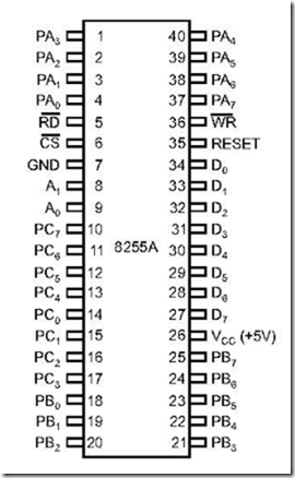
1. Draw the pin diagram of PPI 8255.
Ans. The pin diagram of 8255 is shown in Fig. 9a.1
Fig. 9a.1: 8255 Pin diagram (Source: Intel Corporation)
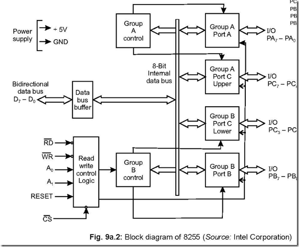
2. Draw the block diagram of 8255.
Ans. The block diagram is shown in Fig. 9a.2.
3. How many ports are there in 8255 and what are they?
Ans. Basically there are three ports in 8255, viz., Port A, Port B and Port C, each having 8 pins. Again Port C can be divided into Ports Cupper and Port Clower— each having four pins i.e., a nibble. Thus 8255 can be viewed to have four ports—Port A, Port B, Port Cupper and Port Clower.
4. What pins are associated with Read/Write control logic block?
Ans. There are six pins associated with Read/Write control logic block. These are CS, WR,
A0, A1, Reset and CS signals.
5. In how many modes can 8255 operate?
Ans. PPI 8255 can operate in three modes. (a) Mode 0 (b) Mode 1 and (c) Mode 2.
Apart from the above, there is another mode called BSR mode (Bit Set/Reset mode).
6. Distinguish between the three modes of 8255.
Ans. The three modes are Mode 0, Mode 1 and Mode 2. These are I/O operations and selected only if D7 bit of the control word register is put as 1.
The three operating modes of 8255 are distinguished in the following manner:
Mode 0: This is a basic or simple input/output mode, whose features are:
z Outputs are latched.
z Inputs are not latched.
z All ports (A, B, CU, CL) can be programmed in either input or output mode.
z Ports don’t have handshake or interrupt capability.
z Sixteen possible input/output configurations are possible.
Mode 1: In this mode, input or outputting of data is carried out by taking the help of handshaking signals, also known as strobe signals. The basic features of this mode are: z Ports A and B can function as 8-bit I/O ports, taking the help of pins of Port C.
* I/Ps and I/Ps are latched.
* Interrupt logic is supported.
* Handshake signals are exchanged between CPU and peripheral prior to data transfer.
* In this mode, Port C is called status port.
* There are two groups in this mode—group A and group B. They can be configured
separately. Each group consists of an 8-bit port and a 4-bit port. This 4-bit port is used
for handshaking in each group.
Mode 2: In this mode, Port A can be set up for bidirectional data transfer using handshake signals from Port C. Port B can be set up either in mode 0 or mode 1.
The basic operations of the three modes are shown below: 7. Which word determines the operating mode of 8255? Ans. A single control word determines the operating mode of 8255.
8. For data transfer using 8255, when mode 0 should be selected? Ans. When unconditional or non-handshaking I/O is required, mode 0 is chosen.
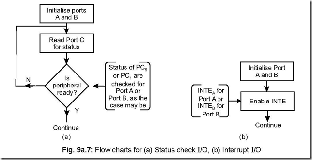
9. How many categories of handshake signals are there? Which is advantageous? Ans. Handshake signals can be used with either (1) status check I/O or (2) Interrupt I/O.
In the status check I/O, the CPU gets tied up in a loop until the status of the I/O
becomes ready while it is the I/O device which interrupts the CPU in interrupt I/O.
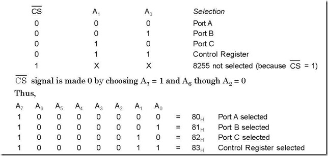
10. Explain how the different ports and control words are selected for 8255.
![]() Ans. The two address lines, along with CS signal, determine the selection of a particular port or control register. This is explained below:
Ans. The two address lines, along with CS signal, determine the selection of a particular port or control register. This is explained below:
11. What is BSR mode and what are its characteristics?
Ans. BSR mode stands for Bit Set Reset mode.
The characteristics of BSR mode are:
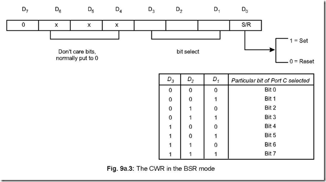
* BSR mode is selected only when D7 = 0 of the Control Word Register (CWR).
* Concerned with bits of port C.
* Individual bits of Port C can either be Set or Reset.
* At a time, only a single bit of port C can be Set or Reset.
* Is used for control or on/off switch.
* BSR control word doesn’t affect ports A and B functioning.
12. Discuss the control word format in the BSR mode.
Ans. The content of the control word register will be as follows, when used in the BSR mode and selects (either Sets or Resets) a particular bit of Port C at a time.
13. Write a BSR control word to set bits PC7 and PC0 and to reset them after 1 second delay.
Ans. To set or reset any particular bit of Port C in the BSR mode, the control word register is to be appropriately loaded. The above is done by loading the accumulator and sending the same to the control register (i.e., by sending the same to the address of the control register). The address of control word register (CWR) is 83H.
Program:
MVIA, 0FH (Accumulator loaded with 0FH to set PC7 bit of Port C) OUT 83H (This sets PC7 bit of Port C)
MVIA, 01H (Accumulator loaded with 01H to set PC0 bit of Port C) OUT 83H (This sets PC0 bit of Port C)
CALL DELAY (Assume the DELAY is for 1 second)
MVIA, 00H (Accumulator loaded with 00H to reset PC0 bit of Port C) OUT 83H (This resets PC0 bit of Port C)
MVIA, 0EH (Accumulator loaded with 0EH to reset PC7 bit of Port C) OUT 83H (This resets PC7 bit of Port C)
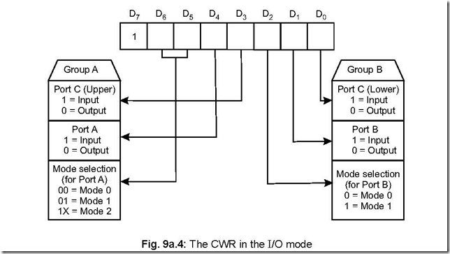
14. Show the control word format for I/O mode operation of PPI 8255. Ans. The control word format, when 8255 is operated in I/O mode, is shown below:
For 8255 PPI to be operated in I/O mode, D7 bit must be 1.
The three ports are clubbed into two groups—Groups A and B. Group A consists of
Port A and CU. Port A can be operated in any of the modes—0, 1 or 2. Group B consists of Port B and CL. Here Port B can be operated in either mode 0 or 1.
15. What happens when RESET pin of 8255 is made high?
Ans. When a 1 is applied on RESET pin of 8255, the three ports are put in the input mode.
All flip-flops are cleared and interrupts are reset. This condition is not altered even when
RESET goes low. 8255 can then be programmed in any mode by appropriately loading
the control word register. The mode operation can be changed by altering the content
of the control word register, whenever needed.
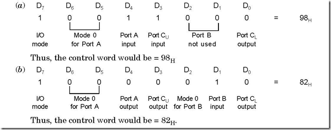
16. Write down the mode 0 control words for the following two cases:
(a) Port A = Input port, Port B = not used, Port CU = Input port and Port CL
= Output port.
(b) Port A = Output port, Port B = Input port, Port C = Output port Ans. The control words for the two cases will be as follows:
17. In mode 1 what are the control signals when ports A and B act as input ports.
Discuss the control signals. Draw the timing waveforms for such a strobed
input.
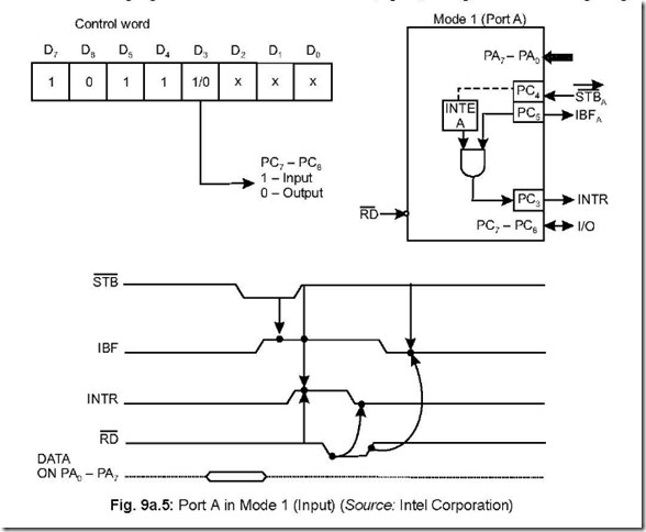
Ans. The following are the control signals when ports A and B act as input ports (under mode 1) STBA , IBFA, INTEA for Port A and STBB , IBFB, INTEB for Port B, respectively. The mdetails about the input control signals are discussed below:
z STB (Strobe input): This is an active low signal generated by a peripheral device.
When a peripheral device has some valid data, it sends the same via Port A or B and
sends a low STB signal. This data is accepted by 8255 and it generates a IBF and INTR
(provided INTE is set previously).
z IBF (Input buffer full): On receipt of STB signal from peripheral device, data is stored
in 8255 by its input latch. In its turn, 8255 generates a high IBF. IBF is reset when CPU reads the data.
z INTR (Interrupt request): This active high output signal is generated only if STB , IBF
and INTE are all set at the same time. This signal interrupts the CPU via its INTR (pin no. 10 of 8085).
z INTE (Interrupt Enable): This is an internal F/F which can be set/reset using the BSR mode. It must be set if INTR signal is to be effective.
The following figure shows Port A in Mode 1 (input), along with the timing diagrams.
18. In mode 1, what are the control signals when ports A and B act as output ports.
Discuss the control signals. Draw the timing waveforms for such a strobed
output.
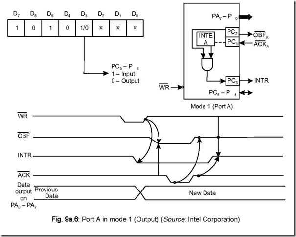
Ans. The following are the control signals when ports A and B act as output ports (under mode 1) OBFA , AC A , INTEA for Port A and OBFB , ACK B , INTEB for Port B
respectively.
The details about the output control signals are discussed below:
* OBF (Output buffer full): This is an active low output signal. This signal becomes low
when the CPU writes data into the output latch of 8255. This output signal from 8255, which goes to a peripheral, indicates to the peripheral that the data on the output latch of 8255 is ready to be read.
*ACK (Acknowledge): When data reading by the peripheral from the output latch of
8255 is complete (i.e., the peripheral has accepted the data), it (the peripheral) outputs ,a low signal which is connected to the ACK (input signal) pin of 8255. On receipt of this low signal by 8255 (from peripheral), the OBF line of 8255 goes high.
*INTR (Interrupt): This signal is set only if OBF , ACK and INTE (internal F/F) are all at high(1) state. This output signal from 8255 goes to INTR (pin 10 of 8085) to interrupt the CPU. The INTR signal is reset on the falling edge of WR .
* INTE (Interrupt Enable): This is an internal F/F which can be set/reset in BSR mode.
This must be set if INTR signal is to be effective.
he following figure shows Port A in mode 1 (output), along with the timing waveforms.
19. In mode 1, what are the methods available for data transfer? Which method is advantageous?
Ans. In mode 1, data transfer is possible involving 8255 when it is programmed to function either in (a) Status check I/O (also called Program Controlled I/O), (b) Interrupt I/O (also called Interrupt Controlled I/O).
In status check I/O, CPU continues to check the status of IBFA or IBFB until they are high. This is done by reading the status word (port C) to check (PC5 for IBFA and PC1 for IBFB) for existence of IBF. It is known as ‘polling’ (reading) the status word. Here it is assumed that both Ports A and B act as input ports.
In interrupt I/O scheme, the status of either INTRA or INTRB (as the case may be) will have to be ascertained to know the port (A or B) which has requested (interrupted) for service. This is done by reading the status of INTRA (PC3) or INTRB (PC0) of the status word. Here again, it is assumed that both ports A and B act as input ports.
Status check I/O is disadvantageous because in this the CPU gets tied up in the loop until the IBF line (IBFA or IBFB, as the case may be) goes high.
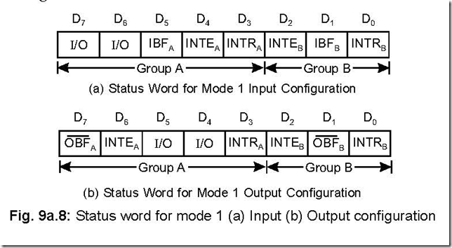
20. Show the mode 1 status word format and discuss.
Ans. There are two mode 1 status word formats—one for input configuration and the other for output configuration. These are shown below:
The mode 1 status format (either input or output configuration) can be read by an input read of Port C.
When 8255 is operated in mode 1, the processor has two choices — either polling or interrupt scheme—this is true irrespective of whether data is inputted to the CPU or otherwise.
When data is inputted (i.e., from peripheral to CPU), the CPU can poll (status check) the IBF line for presence of valid data. Else the processor can be interrupted via the INTR line. To know whether INTRA or INTRB has interrupted can be ascertained by reading the Port C for status of INTRA (bit D3) or INTRB (bit D0).
Again, when data is outputted (by CPU to 8255), again two choices are there. The
CPU can poll the OBF or else be interrupted by INTR line.
If interrupt driven scheme is followed, then INTE (either INTEA or INTEB) has to be previously set in BSR mode.
A confusion arises when interrupt driven I/O scheme is undertaken. For input
configuration, it is seen that STBA signal is connected to PC4 and INTEA is controlled by PC4. For Port B, the corresponding bit is PC2—i.e., STBB is connected to PC2 and INTEB is also controlled by PC2. But this poses no problem because INTE is set/reset in
BSR mode and the BSR control word has no effect when ports A or B are set in mode 1.
21. Discuss the mode 2 of PPI 8255 in brief.
Ans. This mode is usually used for transferring data between two computers.
When operated in mode 2, only Port A can be used as a bidirectional 8-bit I/O bus, using PC3 – PC7 for handshaking. Port B can be programmed only in mode 0 (PC0 – PC2 as input or output) or in mode 1 (PC0 – PC2 used as handshaking signals).
22. How many possible combinations of 8255 would be there when it is operated in mode 2.
Ans. Only Port A can be operated in mode 2 and Port B in either mode 0 or mode 1.
Thus, there would be four possible combinations in mode 2. These are:
(a) Mode 2 and Mode 0 (input)
(b) Mode 2 and Mode 0 (output)
(c) Mode 2 and Mode 1 (input)
(d) Mode 2 and Mode 1 (output)
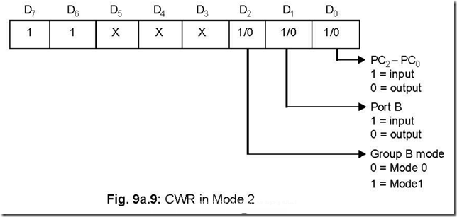
23. Discuss the Mode 2 control word.
Ans. The mode 2 control word is as shown below:
This control word is to be loaded into the control port to configure 8255 in mode 2. Bit D0 of control port determines the I/O operations of PC2 – PC0. D1 bit indicates the Port B input/output operation whereas bit D2 determines Group B to be either in mode 0 or in mode 1 operation.
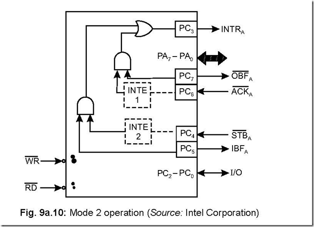
24. Draw Port A and the associated control signals when 8255 is operated in mode 2.
Ans. This is shown in the following figure:
25. What are the output control signals in mode 2 and discuss them?
Ans. The output control signals in mode 2 are OBF , ACK and INTE 1. These control signals are discussed below: OBF stands for output buffer full, an active low signal. In its active condition (i.e., low), it indicates that the CPU has written data into Port A. ACK , an active low signal, stands for acknowledge. This acknowledgement signal is generated by a peripheral and it enables the tri-state output buffer or Port A and makes Port A data available to the peripheral.
INTE 1 is an internal F/F associated with output buffer full. INTE 1 can be used to enable or disable the interrupt (INTR) by setting or resetting PC6 in BSR mode.
26. What are the input control signals in mode 2 and discuss them?
Ans. The input control signals in mode 2 are STB , IBF and INTE 2. These control signals
are discussed below:
STB (strobe input), an active low signal, enables Port A to latch the data available
at its input. This happens if STB = 0.
IBF (Input buffer full), an active high signal, indicates the data has been loaded into the input latch of Port A. This happens if IBF = 1.
INTE 2 is an internal F/F associated with input buffer full. INTE 2 can be used to enable or disable the interrupt (INTR) by setting or resetting PC4 in BSR mode.
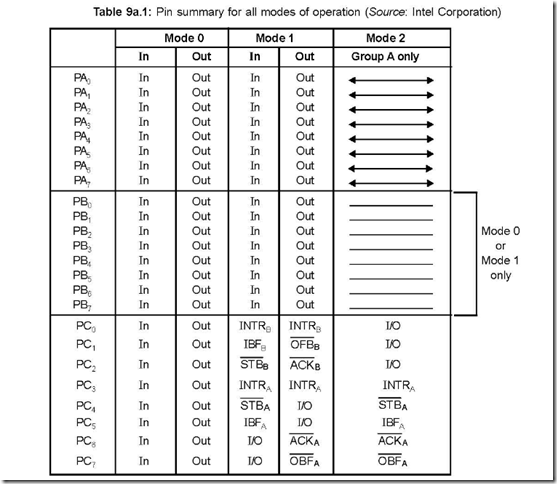
27. Draw a table that summarises the pin functions of Ports A, B and C for various modes of operation.
Ans. The following table shows the pin summary of Ports A, B and C for various modes of operation.
28. What are the status of Port A outputs until they are enabled.
Ans. Port A outputs remain in the tri-state condition until they are enabled. This enabling is done by a low on the ACK signal generated by a peripheral.
29. On which line interrupts are generated in mode 2 for both input and output operations?
Ans. The same (INTRA) is generated on PC3 line, for both input and output operations.
30. Draw the status word in mode 2 and discuss.
Ans. The status word in mode 2 is as shown:
This status word is accessed by reading Port C. D7 – D3 bits of the status word carry the status of OBFA , INTE 1, IBFA, INTE 2, INTRA. The status of the remaining three
bits i.e., D2 – D0 depend on the mode setting of Group B. If Group B is programmed to be in mode 0, then D2 – D0 are simply PC2 – PC0 (simple I/O). But if Group B is in mode
1, then the three bits D2 – D0 carry the information about the control signals for Port
B—and they depend on whether B is acting as an input port or output port.
31. What are the types of devices with which data transfer takes place via the 8255 PPI?
Ans. The input devices from which data are read and delivered to the microprocessor via the input ports of 8255 PPI are ADCs, keyboards, control signals from process devices, paper tape readers, etc.
The output devices to which data are delivered via the output ports of 8255 are DACs, printers, video display, plotters, etc.
32. What kind of functions do the input and output ports play?
Ans. A port, whether an input or an output port, is a set of D F/Fs consisting of several pins in parallel. When used as input pins, they act as buffers and when used as output pins, they act as latches.

In mode 2 of 8255 PPI , what are the methods available for data transfer?