UPFEED ONE-PIPE SYSTEM
One-pipe steam heating systems can also be of the upjeed type. In a standard upfeed one-pipe steam heating system both the steam and condensation travel through the same pipes, and the heat emi,tting units are located above the supply mains (hence the name “upfeed” system).
An attempt to reduce the amount of condensation return in the pipes carrying the steam has resulted in a modification of the upfeed one-pipe system. In the modified system, the condensation is dripped at each radiator (and therefore from the main itself) into a wet return.
The upfeed one-pipe system shown in Figs. 4 and 5 consists of a main or mains branching off from ·the boiler steam outlet and inclined downward, instead of upward in the previously described one-pipe system. This arrangement causes •the condensation in the mains to flow in the same direction as the steam.
The mains connect with return pipes which carry all the condensation back to the boiler, and it is only in the risers .that reverse flow of the condensation ·takes place, and they accordingly should be large enough to take care of this reverse flow without undue turbulence.
Steam from the boilers flow through the main or mains and accruing condensation with it, the condensation returns (hence the name) to the boiler at a much lower level as shown in Figs 4 and 5. After traversing ·the mains, steam flows through the risers and into the radiators. Condensation takes place in warming the radiators and drains through the risers and return pipes to boiler.
A distinction is made between a wet (or sealed) return and a dry return. A wet return is below the water level in the boiler whereas a dry return is above the water level. The advantage of a wet return is that it seals and prevents steam at a slightly higher pressure entering the return. Under most circumstances, a wet return is preferable ·to a dry return. The latter is necessary to clear doorways or other openings.
There are no disadvantages ·to a wet return when the system is properly installed and the valves maintained in tight condition. In most installations, these requirements are often lacking, resuH ing many non-inherent disadvantages. Among the installation problems that should be avoided are: ( 1) pipes too small for the job; (2) sharp turns; (3) air pockets; (4) not enough pi•tch to the mains; (5) not enough air valves; and (6) air valves that are too small or cheap.
UPFEED ONE-PIPE RELIEF SYSTEM
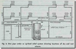
Fig. 6 shows an upfeed one-pipe relief system applied to an eight radiator installation. Connected to the main outlet A are two or more branch mains AB and AC, which supply the various risers. Steam is supplied to each riser, the condensation draining in the riser in reverse direction to the steam flow.
The condensation returns from 1the risers to the boiler by gravity through drip pipes which are virtually continuations of the return pipe so that the condensation will flow back into the boiler.
Steam (usually at from 1 to 5 lbs. gauge pressure) passes from ·the boiler to mains AB and AC. These branches being slightly inclined, any condensation will drain into the drip pipes. The steam passes through the risers to the radiators, where its heat is radiated in warming the rooms, .thus causing condensation. The risers being of liberal size the condensation is carried by gravity in a direction reverse (that is, opposite) to the direction of the steam flow, and drains down the drip pipes, and returns to the boiler through the low level return pipe.
The condensation is forced back into the boiler by the pressure resulting from the greater head of the column of condensation in the drip pipes, as compared with the head of water in the boiler. Moreover, the water in the drip pipes being at a lower temperature than the water in the boiler is heavier which upsets the equilibrium of the two columns.
This system is characterized by a slight difference in pressure (pressure differential) in the different parts of the system due to frictional resistance offered by the pipe to the flow of ·the steam. The steam flow is variable in different parts of the system due to variable condensation and badly proportioned pipe sizes. This can be explained by Fig. 6. If the water level in the boiler is at D, then in operation with wet returns, the pressure difference will be balanced by the condensation standing at different levels in the different drip pipes, as at E and F, these levels being such that the difference in head and density will restore equilibrium. The effect of a wet return can be obtained with the dry return shown at the left, in Fig. 6, by attaching a siphon to .the boftom of the drip pipe. Water from the drip falls into the loop formed by the siphon and after it is filled, overflows into the dry return.
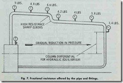
The water will rise to different heights, G and H, in the legs of siphon to balance the difference in pressure at points P and P’. If the siphon were omitted and the drip pipe connected direct to the dry return, there would be a tendency for the condensation in the dry return to back up instead of draining into the boiler,because the pressure in the drip pipe at P, is greater than the pressure in the dry return. In general, the pressure varies because there is a gradual reduction in pressure as the steam flows from the boiler to the remote pafts of the system. This is caused by frictional resistance offered by the pipe and fittings (Fig. 7).
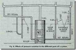
The steam flows into the pipes only when condensation is taking place. The variation in pressure exists, on the other hand, only when the steam is flowing in the pipes. The effects of pres sure variation can be explained with the aid of Fig. 8. With the plant in operation and condensation is taking place in the radiators and draining into the drip pipes-suppose the pressure in the boiler is 5 lbs. gauge; 4 lbs. in drip 1; and 3 lbs. in drip 2, then to balance these pressure differences the water will rise in drip 1 to (L) 2.3 ft. above the water level in the boiler, because ·there is a pressure difference of 1 lb. ( 5 – 4) and the weight of a column of water 2.3 ft. is 1 lb. for each square inch of cross sec tion . Similarly , for drip 2, the pressure difference is 2 lbs. hence, the water will rise in this column to an elevation above the water level in the boiler equal to 2.3 X 2 or 4.6 ft. to balance the 2 lbs. pressure difference. Strictly speaking, these figures are correct only when the temperature of the water in the two drip pipes is the same as the temperature of the water in the boiler. For simplicity, the difference in weight or density of the “cold” water in the drips and hot water in the boiler were not considered. Under these circumstances , the heavy cold water in the drips would rise to lower elevations than those shown at (L) and (F) in Fig. 8.
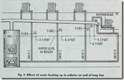
Sometimes there are problems encountered on long lines with radiators located at the end of the line and near the level of the water in the boiler. On long lines where there is considerable reduction of pressure, the water sometimes backs up into the radiator, as in Fig. 9, interfering with its operation.
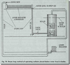
Radiators located at elevations below the water level in the boiler may be operated by means of a steam loop (Fig. 10). In the steam loop, the condenser element may consist of a pipe radiator placed on the floor above the boiler. The liberal conden sing surface thus provided will render the loop very active in removing the condensation and at the same time the heat radiated from the condenser is utilized in heating. The drop leg is pro vided with a drain cock (D) and the connection to the boiler with a check valve. To start the system, turn on the steam at {he boiler and open (D) until the steam appears. The condensation of steam in the condenser (upper radiator) will cause a rapid circulation in the riser, carrying with it the condensation from the radiator, which, in passing over the goose neck, cannot return, but must gravitate through the upper radiator and drop leg past the check valve and into the boiler. The pipe at the bottom of the main riser which acts as a receiver for the condensation from the lower radiator should be one or two sizes larger than the pipe in the main riser.


