Steam is a very effective heating medium. Until recently, this property of steam has resulted in its being the most commonly used method of heating residential, commercial, and industrial buildings. Over the past forty years or so, steam heating has been largely re placed in residences and small buildings by other types of heating systems which have often proven to be less expensive to install and operate, or which operate at similar or greater levels of efficiency in small structures.
The basic operating principles of s·team heating are relatively
simple. A boiler is used to heat water until it turns to steam. When the steam forms, it rises through the pipes in the heating system to ·the heat emitting units (radiators, convectors, etc.) located in the various rooms and spaces in ,the structure. The metal heat emitting units, being cooler, cause the steam to con dense and return to the boiler in the form of water (condensation) for reheating.
CLASSIFYING STEAM HEATING SYSTEMS
There are a number of different methods of classifying steam heating systems, but the most commonly used ones include one or more of the following features:
1. Pressure or vacuum conditions,
2. Method of condensation flow to ·the boiler,
3. Piping arrangement,
4. Type of piping circuit,
5. Location of condensation returns.
Steam heating systems can be divided into low pressure and high pressure types depending on the operating pressure of the steam used in the system. A low-pressure system commonly operates at a pressure of 0 to 15 psig; whereas a high-pressure system will use operating pressures in excess of 15 psig.
Both vapor and vacuum steam heating systems operate at low pressures (i.e. 0 to 15 psig) and under vacuum conditions. The latter type system uses a vacuum pump to maintain :the vacuum; the vapor system does not , relying instead on ·the condensation of the steam to form the vacuum.
The condensation from the heat emitting units is returned to the boiler either by gravi.ty or some sort of mechanical means. When the former method is used, the system is referred to as a gra vity return sy stem. If mechanical means of returning ·the con densation are employed, the system is referred to as a mechanical return system. The ·three types of mechanical devices used to return the condensation in mechanical return systems are:
( 1) the vacuum return pump ,
(2) the condensation return pump, and
(3) the alternating return trap. Each of these devices is described in the appropriate sections of this chapter.
Using ·the piping arrangement as a basis for classification, a steam heating system will be either a one-pipe or a two-pipe system . A one-pipe system is designed with a single main which carries the steam to the heat emitting units and the condensation back to the boiler. In other words, it functions as both a supply and a return main. In a two-pipe system, there is both a supply main and a return main .
The piping circuit may best be described as the “path” taken by the steam to the riser (or risers). In a divided circuit installa tion, two or more risers are provided for the steam supply. A one-pipe circuit installation, on .the other hand, employs a single riser from the boiler to carry the steam supply to ·the heat emitting units. A loop-circuit installation is used when it is necessary to operate heat emitting units at locations below ·the water level of the boiler.
A steam heating system may also be classified according to the direction of steam flow in ·the risers (i.e. supply mains). An up-feed system is designed so that the risers are below the heat emitting units. In other words, the steam supply moves from the boiler up to the heat emitting units in the rooms and spaces within the structure. An up-feed system is also sometimes referred to as an up-flow or under-feed system. A downfeed system is one in which the steam supply flows down ·to the heat emitting units. In this type system, the supply main is located above the heat emitting units.
Sometimes the location of the condensation return is used as a basis for classifying a steam heating system. If the condensation return is located below the water level in the boiler, it is referred to as a wet return. A dry return is a condensation return located above the water level line.
GRAVITY STEAM HEATING SYSTEMS
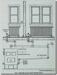
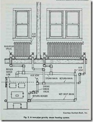
A gravity steam heating system is characterized by the fact that the condensation is returned to the boiler from the heat emitting units by means of gravity rather than mechanical means. Both one- and two-pipe installations are used with .the former being the oldest and most commonly used for a number of years. (Figs. 1 and 2). Gravity systems are generally limited to resi dences and small buildings where the heat emitting units can be located at least 24 inches above the water level line of the steam boiler.
Gravity steam heating systems are the cheapest and easiest to install because ·they are adaptable to most types of structures, but they do have a number of disadvantages inherent t0 the system. The principal disadvantages of gravity steam heating systems are:
1. The return lines in one-pipe gravity systems must be large enough to overcome the resistance offered by the steam flowing up from the boiler in the opposite direction.
2. There is .the possibility of water hammer developing in one-pipe systems, because the steam and condensation must flow in opposite directions in the same pipe.
3. Air valves (which are required) sometimes malfunction by either spurting water or failing to open. If the latter situation is the case, excess heat will build up in the sytem.
4. Automatic control of the steam flow from the boiler results in room temperature fluctuations.
5. Comfortable room temperatures are possible by manually regulating the valves on individual heat emitting units, but this results in some inconvenience.
6. In two-pipe gravity systems, the condensation return from each heat emitting unit must be separately connected to a wet return or water sealed. This is expensive.
The principal reason for the development of the two-pipe gravity system is to create a means of overcoming the resistance offered by the steam flow to the condensation returning to the boiler.
ONE-PIPE REVERSE FLOW SYSTEM
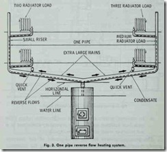
The one-pipe reverse flow system is the simplest and cheapest of this type ·to install. This system is easily distinguished by the absence of any wet or dry returns to the boiler. Supply mains from the boiler are inclined upwards and connect with the room heat emitting units, there being no other piping. This system is called “reverse flow” because the condensation flows back through the mains in a reverse direction or opposi.te to that of the steam flow.
The operation of a ·typical one-pipe reverse flow system is shown in Fig. 3. Steam from the boiler flows into the main or mains (inclined upward) through the risers to the heat emitting units at the bottom. The steam pushes the air out of the mains, risers, and heat emiHing units, and escapes through air valves placed at the other end of the heat emitting units as shown. The condensation forming in the units flows back to the boiler through the same piping, but in the opposite or reverse direction to the steam flow.
For satisfactory operation, every precaution should be used to install the correct pipe sizes, especially for the mains. If the piping is too small, it will be necessary to carry excess pressure in the boiler to insure proper operation. Without the excess pressure, operation of the remote heat emitting units will be unsatisfactory. Satisfactory operation of these remote units can be achieved without excess boiler pressure if the pipes used in the system are the correct size.
The smaller the main the greater the speed of the steam flow and the greater the resistance to the flow of condensation. It is very difficult for the condensation to flow back to the boiler against the onrushing steam in a long main that is in an almost horizontal position. The main should be inclined as much as conditions in the basement will permit.
Leaky radiator valves can be a problem. When the valve does not close tightly, steam will work its way into the radiator and stop the condensation from coming out. The result is that the radiator soon fills with water and when turned on again there is difficulty getting the condensation out. This produces gurgling, hissing and the more violent effect known as “water hammer”.
CLOSED VAPOR SYSTEMS
A vapor system with a return line closed to the atmosphere is sometimes referred to as a closed vapor system. The condensation returns by gravity flow to a receiving device (an alternating re ceiver or boiler-return trap), where it is discharged into the boiler. The condensation from the alternating receiver is discharged against the boiler pressure.
Because air cannot enter a closed vapor system, a moderate vacuum is created by the condensing steam. As a result, steam is produced at lower temperatures and the system will continue to provide heat after the boiler fire has died down.
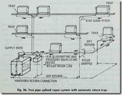
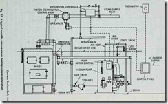
Fig. 26 shows the arrangement of a typical upfeed two-pipe vapor system with an automatic return trap. The heat emitting units discharge their condensation through thermostatic traps to the dry return pipe. These systems operate at a few ounces pres sure and above, but those with mechanical condensation return devices may operate at pressures upward of 10 lbs. per square inch . The simplest method of venting the system consists of a 3A inch pipe with a check valve opening outward. Most systems employ various forms of vent valves, which allow air to pass and prevent its return. A dry return is provided so that the air will easily go out the vent pipe.
VACUUM STEAM HEATING SYSTEMS
A vacuum steam heating system is one which operates with steam at pressures less than that of the atmosphere. The object of such systems is to ,take advantage of low working temperatures of the steam at these low pressures, giving a mild form of heat such as is obtained with hot water heating systems. Vacuum systems such as :these which operate at all ,times at pressures less than atmospheric should not be confused with the combined atmos pheric and vacuum systems described in the next section. There are distinct design differences between the two.
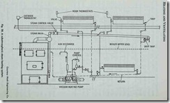
A distinction should be made between a vacuum system and a subatmospheric system. The latter differs from an ordinary vacuum system in that they maintain a controlled partial vacuum on both the supply and return sides of the system, instead of only on the return side. In the vacuum system, steam pressure above that of the atmosphere exists in ,the supply mains and heat emitting units practically at all times. The subatmospheric system is charac terized by atmospheric pressure or higher existing in the steam supply piping and heat emitting units only during severe weather (Figs. 27 and 28).
There are a number of different methods of classifying vacuum systems (e.g. one-pipe or two-pipe, vacuum pressure or sub atmospheric, etc.). For the purposes of this chapter they will be classified according to the type of vacuum: natural vacuum systems and mechanical vacuum systems.
NATURAL VACUUM SYSTEMS
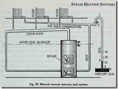
Any standard one- or two-pipe steam system may be converted into a natural vacuum system by replacing the ordinary air valve with a mercury seal, or connecting thermostatic valves to the radiator return outlet on radiators and providing a damper regu lator on coal burning boilers adapted to vacuum working. The mercury seal system is shown in Fig. 29.
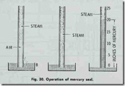
A mercury seal is virtually a barometer consisting (as shown in Fig. 30) of a tube (A) which dips just below the surface of the mercury in a cup (B). When the steam is raised in the boiler to pressures above atmospheric, it drives all air out of the system, the air leaving by bubbling through the mercury in cup (B).
If the fire is allowed to go out, the steam will condense and produce a vacuum, provided all pipe fiHing has been carefully done and the valve stuffing boxes are tightly packed.
In Fig. 29 the loop at (C) prevents water being carried over into the seal pipe when purging the system of air. If air should again enter the system, it can be expelled by raising the steam pressure above atmospheric. In very cold weather, ·the system can be operated at pressures above atmospheric by closing valve (D). When fires are banked for the night, valve (D) may be opened and the system worked as a vacuum system. The flexibility of vacuum systems is in sharp contrast with low pressure systems where steam disappears from ·the radiators as the temperature drops below 212 °F. According to weather demands, the radiators may be kept at any temperature from say to 150°F. to 220°F.
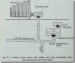
Another method for maintaining a natural vacuum is by using thermostatic valves instead of a mercury seal. A thermostatic valve is one having an expansion element which operates to close the valve when heated by hot steam and to open .the valve when chilled by the relatively cold condensation.
The two kinds of thermostatic valves used are the single unit (or retainer) valves and two unit or combined retainer and air check valves sometimes called master thermostatic valves.
Fig. 31 shows the details of a master thermostatic valve, con sisting of a thermostatic unit and an air check. The thermostatic unit has an expanding element, the air check consisting of a group seat poppet check valve that is practically air tight and will retain the vacuum within the system for a considerable length of time.
The air check operates when excess pressure is generated in the boiler to purge the system of air, the check at other times re maining closed.
The thermostatic valve remains open while the system is being purged of air and condensation but closes when steam enters the valve chamber-it retains vacuum in the air line.
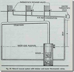
Fig. 32 shows the operation of the natural vacuum system with retainer and master thermostatic valves. Individual thermostatic retainer valves (A, B and C) are placed in the outlet of each radi ator which pass air or water, but close to steam. At the end of the air line is a master thermostatic valve (D), which operates when the system is purged of air by excess pressure.
The drip should be proportioned to prevent water entering the air line in case of high vacuum in such a manner that the ver tical distance (M), between water level in the boiler and the lowest point of air line is not less than two feet for each inch of vacuum .to be carried in the system.
The successful operation of natural vacuum systems depend3 largely on efficient damper regulators on coal burning boilers (i.e. efficient draft control), for unless the fire is held in proper check, the pressure will rise and break the vacuum. This can waste fuel, for there may be sufficient heat in the boiler to supply steam to the system with a five, or even ten inch vacuum and hold that heat in the system for hours.
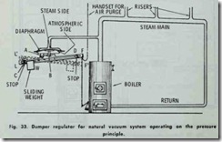
Automatic damper regulators are designed to act by pressure, temperature or a combination of these two. Fig. 33 shows a regu lator which acts on the pressure principle. It consists of a dia phragm connected at (B) to a lever fulcrumed at (A) and having a weight (W) free to slide along a slot between the stops.
In starting, the weight is placed on the left side of the lever as shown (Fig. 33). This tilts the lever (position LF) and opens the damper. The weight is adjusted by the stop so that sufficient pres sure is produced to clear the system of air before the regulator trips to position (L’F’) (shown in dotted lines) and closes the damper.
The regulator is gradually closing as the pressure comes on. When entirely closed, the weight slides to the right and remains in this position until the vacuum in the system becomes strong enough to gradually open the damper-just enough to maintain a vacuum.
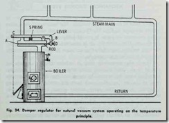
In the morning, the regulator may be set to open position from the floor above by .the pull chain (M). This generates pressure and purges the system of any air which might have accumulated, and then the regulator weight automatically goes to the vacuum side of the regulator and maintains .the vacuum heat until more fuel is required or further regulation necessary. Temperature controls or damper regulators which depend on temperature changes for their operation may also be used (Fig. 34). Since the temperature of steam increases with the pressure, evidently the expansion and contraction of a rod exposed to ·the steam can be made to operate the damper.
Fig. 34 shows the construction of a typical ;thermostatic regulator. The “expansion element” or rod is fastened at (A) in a closed cylindrical chamber through which steam from the boiler passes to the main. The end (B) is free to move, passing out of the chamber through a stuffing box. The motion of the rod is considerably magnified by the bell crank lever, which is connected to the damper by a chain attached at (C).
In operation, as the pressure of the steam rises, so does its temperature and the rod (which is made of a metal having a higher coefficient of expansion than that of the cylindrical chamber) end (B), will move to the right, thus causing end (C) of the lever to descend, closing the damper.
When the pressure falls, .the rod contracts and ·the spring which keeps the bell end in contact with the rod causes end (C) of the lever to rise and open the damper.
The level will assume some intermediate position in actual operation, thus holding the steam at some pre-determined pressure. which may be varied by means of the screw adjustment(D).
The major objection to regulation by .temperature is that there is no provision for securing excess pressure to purge the system of air in starting. This must be done by hand control of the damper. This objection can be overcome by ·the method of combined pres sure and temperature regulation, which employs pressure for start ing and temperature for running. In starting, the thermostatic por tion of the regulator is closed off from •the system during which pressure is generated sufficient (about one pound) to purge the air from ·the system. After purging, the regulator automatically opens a valve to the thermostatic position, which then maintains the temperature desired, its range embracing both vacuum and low pressure operation.
