MULTIPLE TAPPED WINDINGS
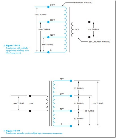
It is not uncommon for transformers to be designed with windings that have more than one set of lead wires connected to the primary or secondary. The transformer shown in Figure 19–18 contains a secondary winding rated at 24 volts. The primary winding contains several taps, however. One of the primary lead wires is labeled C and is the common for the other leads. The other leads are labeled 120, 208, and 240, respectively. This transformer is designed in such a manner that it can be connected to different primary voltages without changing the value of the secondary voltage. In this example, it is assumed that the secondary winding has a total of 120 turns of wire. To maintain the proper turns ratio, the primary would have 600 turns of wire between C and 120; 1,040 turns between C and 208; and 1,200 turns between C and 240.
The transformer shown in Figure 19–19 contains a single primary winding. The secondary winding, however, has been tapped at several points. One of the secondary lead wires is labeled C and is common to the other lead wires. When rated voltage is applied to the primary, voltages of 12, 24, and 48 volts can be obtained at the secondary. It should also be noted that this arrangement of taps permits the transformer to be used as a center tapped trans- former for two of the voltages. If a load is placed across the lead wires labeled C and 24, the lead wire labeled 12 becomes a center tap. If a load is placed across the C and 48 lead wires, the 24-lead wire becomes a center tap.
In this example, it is assumed the primary winding has 300 turns of wire. In order to produce the proper turns ratio, it would require 30 turns of wire between C and 12, 60 turns of wire between C and 24, and 120 turns of wire between C and 48.
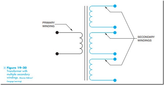
The transformer shown in Figure 19–20 is similar to the transformer in Figure 19–19. The transformer in Figure 19–20, however, has multiple secondary windings instead of a single secondary winding with multiple taps. The advantage of the transformer in Figure 19–20 is that the secondary windings are electrically isolated from each other. These secondary windings can be either step-up or step-down depend- ing on the application of the transformer.

