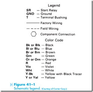
In the previous units, basic symbols and rules for reading a schematic diagram have been covered. In actual practice, however, schematics do not always look like the classic textbook examples. Many schematic diagrams use a legend to aid in understanding. A legend is a list that shows a symbol or notation and gives the definition of that symbol or notation. The legend that will be used with the schematics presented in this unit is shown in Figure 41–1.
SCHEMATIC 1
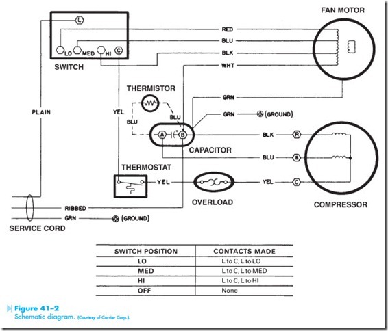
The first circuit to be discussed is shown in Figure 41–2. First find the major components shown on the schematic: the switch, fan motor, compressor, capacitor, overload, and thermostat. Notice that these components may not be shown exactly as
you would expect. Notice the overload symbol, for example. The symbol used is the same as the symbol for an overload heater discussed earlier in the text. There are, however, no overload contacts shown. The schematic is indicating the use of a small, single- phase bimetal overload unit that acts as both heater and overload contact.
Next, find and examine the fan motor. Notice that this motor has several windings that indicate that it is used for multispeed operation. Notice also that there is no capacitor connected to this motor. The small winding shown separate is the start winding. Because there is no start or run capacitor shown, this motor is a resistance start induction run. Notice that the white wire is connected from the motor to B terminal of the capacitor and then to one lead of the service chord. This indicates that the white wire is common to the other windings. Now trace the connection of the red, blue, and black wires. The red wire is connected to the LO speed position on the switch; the blue wire is connected to the MED speed position and the black wire is connected to the HI speed position.
Next, examine the compressor. Notice that two windings are shown. Each winding is connected to a terminal. One terminal is labeled with an R to
represent the run winding. The middle terminal is labeled with an S, which represents the start winding terminal, and the third terminal is labeled with a C, which indicates the common terminal. Trace the common terminal through the overload and thermostat to terminal C on the switch. Notice that the thermostat and overload are connected in series with the compressor. Now trace the run lead of the compressor. Notice that it is connected to the B terminal of the capacitor. This shows that the run winding is connected to the common side of the service chord. Now trace the start lead to the A side of the capacitor. Notice that the capacitor is connected in series between the common side of the service chord and the start winding. The thermistor connected across the capacitor terminals is used to decrease the capacitance connected in series with the compressor after the compressor is in operation. Recall that a thermistor is a temperature-sensitive resistor. This thermistor has a negative temperature coefficient, which means that it will have a very high resistance when it is cool. When its tempera- ture increases, its resistance will decrease. When the compressor is first started, the thermistor is cool because no current has been flowing through it. This causes its resistance to be much greater than the capacitive reactance of the capacitor. The full amount of the capacitor is now connected in series with the start winding.
As current flows through the thermistor, its temperature begins to increase. This causes a decrease in its resistance, which permits more current to flow. As the resistance of the thermistor decreases, the effect of the capacitor on the motor decreases also. The effect is very similar to having a compressor that has both a start and run capacitor in the circuit for starting, and then disconnecting the start capacitor and permitting the motor to operate with the run capacitor only.
The last component to be discussed is the switch. Notice that it is not shown with internal electrical connections. There is a legend at the bottom of the schematic, however, that shows which terminals are connected when the switch is set in different positions. In the LO position, for example, terminal L is connected to both the LO fan speed position and the C position, which permits the thermostat to control the compressor.

