Pipe Fitting Measurements
Pipe fitting may be done either by making close visual judgments or entirely by measurements scaled on a drawing. The first method is a hit-or-miss process and requires an experienced fitter to do a good job; the second method is one of precision and is the better way. In actual practice, a combination of the two methods will, in some cases, save time and give satisfactory results.
Working from a drawing with all the necessary dimensions has certain advantages. Especially in the case of a big job, all the pipe may be cut and threaded in the shop so that at the place of installation the only work to be done is assembling.
In making a drawing, the measurements are based on the distances between the centers of fittings. The data necessary to locate these centers are given in a more general dimension drawing with an accompanying table such as the one illustrated in Table 8-16. These dimension drawings and tables should be the ones corresponding to the make of fittings used; otherwise, there might be the possibility of slight variation. In general, however, the different makes are pretty well standardized.
Figure 8-4 illustrates how the actual length of pipe connecting the two fittings is obtained. The actual length of pipe is equal to the distance between centers (of fittings) minus twice the distance from the center of the face of the fittings plus twice the allowance for threads. This is expressed by the following equation:
D A – 2B + 2C
The allowance for the length of thread that is screwed into the fit- ting (dimension C in Figure 8-4) is obtained from a table furnished by the manufacturer. This allowance (called A in Figure 8-5) corresponds to the values given in the accompanying table (see Table 8-17). Note that the dimension A in Figure 8-5 is the same as dimension C in Figure 8-4.
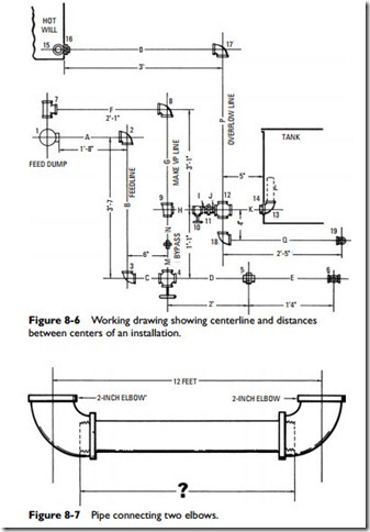
A working drawing showing centerlines and distances between centers of an installation is shown in Figure 8-6. This gives all the information except the actual length of the pipes.
Problem
Find the length of the pipe connecting the 2-inch elbows in Figure 8-7.
Using Figure 8-4 as a guide, the following dimensions are provided: A
12 ft, B 21⁄4 in, and C 11⁄16 in. The problem is solved as follows:
Calculating Offsets
In pipe fitting, an offset is a change of direction (other than 90°) in a pipe bringing one part out of (but parallel with) the line of another.
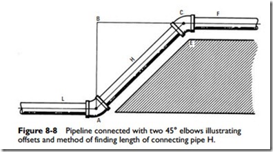
An example of an offset is illustrated in Figure 8-8. As shown here, the problem is an obstruction (E), such as a wall, blocking the path of a pipeline (L). It is necessary to change the position of pipeline L at point A to some parallel position such as line F in order to move around the obstruction. When two lines such as L and F are to be piped with elbows other than 90° elbows, the pipe fitter is confronted with the following two problems: (1) finding the length of pipe H and (2) determining the distance BC. By determining the distance BC, the pipe fitter will be able to fix point A so that the two elbows A and C will be in alignment.
Of course, in the triangle ABC, the length of pipe AC and either offset (AB or BC) that may be required are quickly calculated by solving the triangle ABC for the desired member, but this involves taking the square root, which is not always easily understood by the average worker. Alternative methods are suggested in the fol- lowing sections.
First Method
If, in Figure 8-8, the distance between pipelines L and F is 20 inches (offset AB), what length of pipe H is required to connect with the 45° elbows A and C?
Based on the triangle ABC, the following equation is offered for solving this problem:
It should be remembered that when 45° elbows are used, both offsets are equal. Therefore, if offset AB is 20 inches long, offset BC also must be the same length.
Note that the value (that is, 28.28 inches) for the length of pipe H obtained by the aforementioned equation is the calculated length and does not allow for the projections of the elbows. In other words, pipe H (as calculated by this equation) is too long and must be shortened so that the elbows will fit.
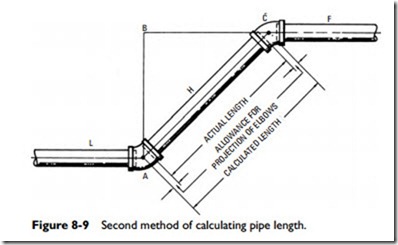
Figure 8-8 illustrates the difference between the calculated length (that is, the measurement from point A to point C) and the actual length of connecting pipe H when used with elbows other than 90°. Actual length is obtained by deducting the allowance for projection of the elbows from the calculated length.
Second Method
Another method of calculating the connecting pipe length (that is, the length of pipe H in Figure 8-9) is by multiplying the offset by 53⁄128 inch and adding the product to the original offset figure. Thus, if offset AB is 20 inches, the following calculations are possible:
Third Method
The pipe fitter will often encounter elbows of angles other than 45°.
For these, the distance between elbow centers (points A and C) can easily be calculated with the following procedure:
1. Determine the angle of the elbow.
2. Determine the elbow constant equivalent to its angle.
3. Multiply the elbow constant by the known offset.
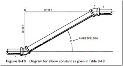
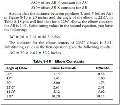
In Figure 8-10, even though only offset AB is known, it is possible to determine the length of the other offset (BC) and the distance between elbow centers (AC). In order to do this, the following equations must be used:
AC offset AB X constant for AC BC offset AB X constant for AB Assume that the distance between pipelines L and F (offset AB) in Figure 8-10 is 20 inches and the angle of the elbow is 221⁄2°. In Table 8-18 you will find that for a 221⁄2° elbow, the elbow constant for AB is 2.41. Substituting values in the second equation, you have the following:
Fourth Method
Offsets may also be calculated by using basic trigonometry.
Using the example given in Figure 8-10, determine the length of the offset AB if AC is 8 feet and the angle <? 60°. From Table 8-19, sine 60° 0.866:
Length of offset AB 0.866 X 8 6.93
Related posts:
Incoming search terms:
- nu vot
- Pipe and Fittings mail
- पाइप फिटिंग फार्मूले
- pipe fitter formula
- fabrication mep convert pipe fitting to design line
- copper pipe fitting allowance
- pipe fitting formulas
- TABLE CENTER FITTING PIP
- what is the face to center distance on a 3/4 inch pipe elbow
- pipe fitter drawing
- estimate the length of pipe elbow
- measuring pipe length between fittings
- how to estimate the nubmber of fittings to use on a pipe that is 40 ft
- 2/5 pipe shortened to 1/7 how much is removed?
- how much thread gose into pipe fitting
- why it is important to measure the piping material to determine how far into the fitting the pipe extends
- pipe lenght with angle
- For threaded fittings the _________ is the distance that the pipe screws into the fitting
- piping fittings measurement
- pipe fitter measurements
- pipe offset method
- distance between fitting hvac
- pipe line offset method
- formula pipe fitter
- पाइप फिटर फार्मूला
- pipe fitter calculations
- Pipe Fitting calculation
- thread pipe drawing
- fittings mail
- Pipe Fitting Measurement Chart
- pipe fitting measurements
- pipe fittings measure calculation
- pipe fitting offset question
- how to work of fitter pipe line
- Example to calculate sizes as a pipe fitter
- pipe fitting drawing
- how to detrimine distance betweentubing 37 degree fittings
- pipe fitting formula
- pipe fitting techniques
- pipes and fitings mail
- how to measure of ms piping
- dimentional measurments are taken from which side of the pipe
- Pipe Fittings Co mail
- pipes fittingsdrawing
- Distance pipes
- How to calculate pipe length with fittings
- calculation of fitting allow
- फिटिंग mail
- Elbow 90° 3D mail
- elbow length formula pipe


