Direct Digital Control of an Air-Handler
In this section we are going to consider a constant-volume air-handler serving a single zone, designated ‘001’. The air handler uses space temperature for control, with no mixed air control, unlike air-handlers that we have discussed before. This is a design choice, unless there is a local code that requires a specific method. Where ASHRAE/IESNA Standard 90.1-2004 Energy Standard for
Buildings Except Low-Rise Residential Buildings3 is incorporated into the local building code requirements, the use of mixed air control is not allowed. We will discus this standard in the next chapter.
To specify a DDC control system, ideally, one produces three things:
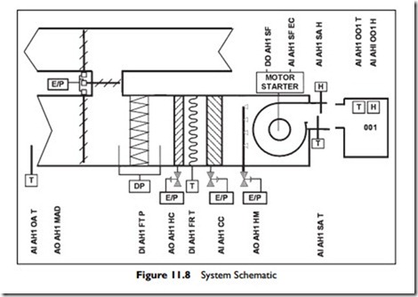
1. A schematic of the system with the control points labeled, Figure 11.8
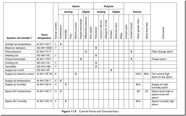
2. A list of control points with their characteristics, Figure 11.9
3. A schedule of operations
The schematic with the points labeled is not always provided, but it can avoid arguments about the location of points after installation, and it provides the maintenance staff with a map for locating points.
Sequence of Operation
Schedule: Provide calendar/time schedule with minimum of three occupied periods each day.
Unoccupied: When calendar schedule is in unoccupied mode, and if space temperature is above 60°F, the fan shall be off, heating valve closed, cooling valve closed. If space temperature falls below 60°F, then the outside dampers and cooling valve to stay closed, heating valve to 100% open, and start fan. When space temperature reaches 65°F, turn fan off and heating valve closed.
Occupied: When calendar schedule is in occupied mode, the fan shall be turned on and after 300 seconds, the heating valve, outside air dampers and cooling coil shall be controlled in sequence to maintain space temperature at 72°F.
The control sequence shall be: heating valve fully open at 0% and going to fully closed at 33%, at 34% the dampers will be at their minimum position of 20% and will move to fully open at controller 66%, the cooling valve will be fully closed until 66% and will be fully open at 100%
Economizer control: When the outside temperature is above 66°F, the outside air dampers shall be set back to minimum position of 20%, overriding the room controller requirement.
Fan Control Alarm: If the fan has been commanded on for 30 seconds, and the fan current is below alarm setpoint 85% of commissioned current, the fan shall be instructed to stop, outside air dampers closed, and heating and cooling valves closed. An alarm of ‘low fan current’ shall be issued.
If the fan has been commanded off for 10 seconds, and the fan current is above the low limit, the fan shall be commanded off, and dampers, heating coil and cooling coil shall be controlled as in occupied mode. An alarm of ‘fan failing to stop’ shall be issued.
Filter alarm: If the filter pressure drop exceeds 0.3 inches water gauge, the filter alarm shall be issued.
Freeze Alarm: If the supply air temperature drops below 45°F, hardware freezestat operates, system changes to unoccupied mode and issues ‘freeze’ alarm.
Manual override: If the manual override is sensed, run in ‘occupied mode’ for 3 hours.
System status: 280 seconds after entering ‘occupied mode’ the room temperature, supply temperature, and ambient temperature shall be recorded along with current date and time.
Note that, in this case, the point names are given in full. It really helps future maintenance if a point naming convention is established and enforced, including having the contractor label every input and every output device with its point name. It also discourages the contractor from accidentally drop- ping into the naming convention of the last project!
The convention used here is only an example, chosen to make this text easy to understand. Many naming conventions do not include the spaces and many do not include the AI, AO, DI, DO but make the name self explanatory. For example, instead of AO AH1 CC, they might use AH1 CCV, meaning AH1 Cooling Coil Valve.
The column ‘Device number’ refers the contractor to the specification for the device. In this case, device number 1 is an outdoor air temperature sensor, device number 2 is a duct temperature sensor, and device number 3 is a room temperature sensor.
Most of the sequence of operations shown here can be achieved with any control system. Two DDC specific routines have been included, to aid maintenance and to help avoid energy waste:
The first is to start the fan leaving all controls alone. The fan will circulate air from the space, so after 280 seconds the sensors should have stabilized The space temperature sensor should record the same temperature as the supply air temperature, except for the small rise in temperature due to fan energy that occurs as the air goes through the fan. Lets suppose this rise is normally 1°F on this example system.
One cool day, when the chilled water system is shut down, the operator checks the startup temperature rise. It is surprising to note that it is minus 4°F, so something has gone wrong. It is cool outside, so the outside dampers could be letting in cold air, even when they are controlled to be fully closed. It is also possible that the space temperature sensor or supply air temperature sensor is providing the wrong reading. The operator does not know which is the actual problem but will probably start by checking the dampers.
The erroneous temperature difference will provide different possibilities for what is wrong under different weather conditions, depending on whether the chilled water was available, and whether the temperature difference was positive or negative. The designer can fairly easily work up a written decision tree of possible problems to help the operator. As all the information is available in the DDC system, the designer can also program the system to work through the decision tree and present the operator with the possible problems to check.
This level of sophistication is becoming available on factory produced standard products. On larger systems, and for remotely monitored sites, this type of self-analysis is becoming a valuable feature of high-level DDC systems. However, it is generally not warranted on a small, simple system where the programming is being written for that one project.
The second specific DDC feature is using a current sensor on one of the cables to the fan to provide a measure of fan current. Our example is a constant volume system, so the load on the fan will be relatively constant. It will not be completely constant, since the pressure drop across the filters will rise as the filters become loaded with dirt. Based on the actual fan cur- rent when the system is commissioned, a high alarm point and a low alarm point can be chosen. Then, if a bearing starts to fail, the load will typically rise, and this can be detected before bearing failure and possible destruction of the fan. Also, if the fan is belt driven and the belts slip or break, the fan current will drop substantially. This will also be detected. Finally, if the fan starter or motor fails, there will be no motor current, again sensed as low current and alarmed.
These are just two examples of how a small change in how the DDC controls are arranged can provide for better control and maintenance.
Now that we have considered the basics of DDC and a sample system we will move on to how systems are interconnected and built up into networks serving a whole building or many buildings.

