Thermodynamics of the 90 IFR turbine:
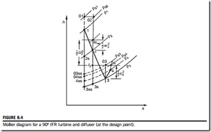
The complete adiabatic expansion process for a turbine comprising (a) the scroll and nozzle blade row, (b) a radial rotor, and (c) a diffuser, corresponding to the layout of Figure 8.3, is represented by the Mollier diagram shown in Figure 8.4. In the turbine, frictional processes cause the entropy to increase in all components and these irreversibilities are implied in Figure 8.4.
Across the scroll and nozzle blades the stagnation enthalpy is assumed constant, h01 5 h02, and, therefore, the static enthalpy drop is
which correspond to the static pressure change from p1 to the lower pressure p2. The ideal enthalpy change (h1 2 h2s) is between these same two pressures but is at constant entropy.
In Chapter 7, it was shown that the rothalpy, I 5 h0;rel 2 ð1=2ÞU2, is constant for an adiabatic irreversible flow process, relative to a rotating component. For the rotor of the 90o IFR turbine,
In this analysis, the reference point 2 (Figure 8.3) is taken to be at the inlet radius r2 of the rotor (the blade tip speed U2 5 Ωr2). This implies that the nozzle irreversibilities are lumped together with any friction losses occurring in the annular space between nozzle exit and rotor entry (usually scroll losses are included as well).
Across the diffuser the stagnation enthalpy does not change, h03 5 h04, but the static enthalpy increases as a result of the velocity diffusion. Hence,


