PROPRIETARY SYSTEMS
Over the years, a number of automatic heating systems have been designed and patented by manufacturers of steam heating equipment. Because these heating systems are protected by patent, they are referred to by the name of the manufacturer. Three of the most popular of these proprietary steam heating systems have been:
1. The Trane Vapor System,
2. The Dunham Differential System,
3. Webster Moderator Systems.
The Trane Vapor System illustrated in Fig. 46 is a combined atmospheric and natural vacuum system installed for residential heating. In this system, the air and water return runs in the same direction and is practically .the same length as the supply main. When properly worked out, ,this feature gives the same effect as though each convector radiator were placed at an equal dis,tance from the boiler. This tends to synchronize the heating effect of all the heat emitting units in the system.
When the fire is started in the boiler of the Trane system, the water becomes heated and steam is formed which flows through the supply main and enters the radiators, displacing the air which is heavier than the steam. The air and condensation drain from the radiators through radiator traps and return piping to a point near the boiler where the air is exhausted through the quick vents (4) and float vents ( 1) at the end of the steam and return mains. The water is returned to the boiler by the direct return trap (2).
As the rooms become warm, less steam is condensed and the pressure in the boiler begins to rise. The rising pressure causes the damper regulator (3) to operate, closing and opening the drafts and maintaining just the amount of pressure necessary for proper heating.
When the fire in the boiler becomes lower, condensation forms and air is prevented from entering the system and a vacuum is created. As a result, the operation changes from atmospheric to natural vacuum; hence the name “combined atmospheric and natural vacuum system.” The reduced pressure of the vacuum allows the water to boil and furnish steam to the radiators at a lower temperature; a decided economy when the fire is low.
The boiler connections for Trane system is shown in Fig. 47. It is very important that the steam connection to the return -trap be taken from .the steam space of the boiler and not from the supply piping of the header. The top of the direct return trap (2) must be placed at least 22 inches above the water line of the boiler. In no case should the top of the trap be less than 4 inches below the air and water return main. The dimensions from the water line to the end of the mains and the top of the return trap are the minimum allowable. Greater clearance above the water line should be employed where possible. Where the ends of the steam and return mains occur in remote parts of the building away from the boiler, use the connections shown in Fig. 48. The ends of such mains must always be vented before dropping to the wet return. The vent pipe must be installed from the piping below the trap up to the return main when a wet return is used. If a dry return is used, the vent pipe may be omitted.
If desired, a Hartford connection may be used between the inlet to the boiler and the return connections from ·the steam and return mains (see HARTFORD RETURN CONNECTION in this chapter) .
The recommended size for vertical piping immediately below the float vents (1) and .the quick vents ( 4) is P-4 inch pipe at least 6 inches long. This affords a separate chamber for air and water.
The connections for a dripping steam main that rises to a higher level are illustrated in Fig. 49. The trap and strainer may be omitted provided the lower main is at least 18 inches above the water line and the return is connected directly into ·the return header of the boiler.
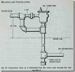
When the motor operated steam valves are used on the mains, the boiler connections should be arranged as shown in Fig. 50. An equalizer line is required to equalize between the steam main and the return main when a vacuum forms in the former after the motor operated valve closes. A swing check valve prevents the flow of steam into the return main (Fig. 51). Fig. 52 shows the ar rangement of boiler connections when air is eliminated from the return main through the No. 9 vent trap. Sometimes reversed circulation resulting from rapid condensation of steam will tend to create greater vacuum in the steam main than in the return main. This can be prevented by using the boiler connections illustrated in Fig. 49.
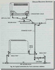
A typical convector radiator used in the Trane system is shown in Fig. 53. It is equipped with an angle valve and an angle trap having horizontal laterals below the floor. Connections for Trane convector radiators are illustrated in Fig. 54. The upper unit shows a vertical trap and a straightway valve concealed within the convector radiator. The lower unit is equipped with an angle valve and trap with a downfeed riser dripped through the angle trap.
The Dunham Differential Vacuum Heating System is a simple two-pipe power vacuum (air pump) return system working nor mally at pressures below atmospheric (subatmospheric) in the system and employing orifice supply valves on the radiators. The principal advantage of the Dunham system is that it continuously distributes heat at a variable rate equal to heat losses from the structure. This is accomplished by reducing the capacity of the system by reducing the volume temperature of the steam.
Standard radiators, pipe fittings, and boiler connections are used in the Dunham system. The principal features of the Dunham system that distinguish it from other heating systems are:
1. The traps and valves,
2. The condensation pump,
3. The controller.
Each of these components is differentially controlled; that is, each is actuated by a pressure differential (the difference in pressure in the supply piping and the pressure return piping). The Dunham system distributes the steam proportionately to all radi ators, the pressure range being from 2 lbs. gauge to pressures considerably lower than atmospheric. Because of the relatively constant differential in pressures between the steam and return lines, the radiators are filled with steam.
A condensation pump is connected to the differential controller and to the supply and return piping. The controller star,ts the pump when the pressure difference between the supply and return piping tends to fall or disappear, and stops it when the pressure differential is restored. The condensation pump is a wet air pump which handles both air and condensation.
The thermostatic radiator traps are actuated by temperature changes within the radiator. Drip traps are installed at drip points to which large volumes of condensation flow. These are combined thermostatic and float traps. A control valve regulates the ad mission of a continuous flow of steam into the heating main.
Webster Moderator Systems are special control systems used primarily with two-pipe vapor, vacuum, and vented return sys tems or in modified form with some one-pipe steam heating systems.
These Webster moderator systems are controlled by the weather with an automatic outdoor thermostat. One or more hand operated variators can be used to adjust the outdoor thermostat. The two types of moderator control systems produced by Webster are based on the following operating principles:
1. Continuous steam flow.
2. Pulsating steam flow.
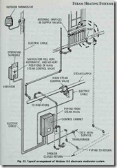
The continuous steam flow arrangement is called :the Webster Electronic Moderator System (Fig. 55), and is suitable for med ium to large buildings requiring one or more control valves. This system consists of the following basic components:
1. Outdoor thermostat,
2. Main steam control valve,
3. Variator.
The steam supply may be taken from a high or low pressure boiler or any other source. The initial pressure should not be over 15 lbs., using a reducing valve if necessary. The return piping may be either open or closed.
The moderator control regulates the pressure difference and will function equally well regardless of whether the pressure in the return piping is at atmospheric pressure or below. The main steam control valve is adjusted automatically by the moderator control which acts to reverse the direction of the motor, causing it to move the valve in the closing direction when less steam is required and in the closing direction when less steam is required and in the opening direction when more s,team is required. The outdoor thermostat automatically varies the steam flow in accordance with changes in outdoor temperature. Depending upon the outdoor temperature, the thermostat automatically selects the position of the main steam control valve. Its position may be advanced or reduced by the variator to give more or less steam than is called for by the outdoor temperature.
Changes in pressure difference in the heating system are auto matically compensated for by a pressure actuated mercury tube in the control cabinet. One end of the tube is connected to the steam supply main and the other end to .the return main. If the supply pressure is unduly increased, mercury rises in the tube to un balance resistances contained therein and the main steam valve begins to close in amount sufficient to balance resistances. A reverse action takes place when the pressure difference falls below that called for by the control equipment.
The pulsating steam flow arrangement is called the Webster Moderator System. This system comprises a central heat control of the pulsating flow type for new or existing steam or hot water systems. It is designed for small and medium size buildings and for zoning of large buildings. It directly controls the operation of burner, stoker, blower or draft damper motors. The basic com ponents of this system are:
1. Outdoor thermostat,
2. Pressure difference controller,
3. Control cabinet,
4. Capillary tubing.
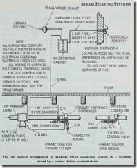
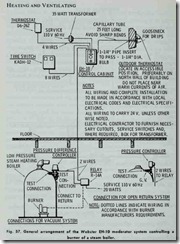
These four components work together to open and close a valve in the steam main or to start and stop the automatic firing device at the boiler generally through a relay. Fig. 56 shows the general arrangement of a Webster EH-10 moderator system for a building served by a central station or street steam. A Webster EH-10 moderator system used for controlling a burner on a steam boiler is illustrated in Fig. 57.
The pressure difference controller maintains the correct pres sure difference between supply and return piping. In combination with metering orifices, this device gives an even distribution of the steam to all radiators in the system thereby preventing over or under heating.
Control is accomplished by varying the length of intervals dur ing which steam is delivered to the radiators. These intervals are longest in cold weather and shortest in mild weather. The timing is such that the longest off interval is comparatively short so that heat output from radiators is practically continuous.
The timing mechanism inside the control cabinet is powered by a synchronous motor which turns a cam. Timing gears between motor and cam set the length of the operating cycle. Rising on the cam is a roller connected to the arm of a switch. When the roller is on the high part of the cam, the switch is in the position for opening the control valve or starting the firing equipment. When the roller is on the low part of the cam, the switch is on the posi tion for closing the control valve or stopping the firing equipment. The length of the ON interval is changed automatically by the out door thermostat or by adjusting the variator by hand. The average length of the cycle is 30 minutes. Other gears can be furnished for cycle lengths from 12 to 60 minutes.
A variator is included in the control cabinet for manual ad justment of the rate of heat delivery to the building. The variator changes the relationship of the switch lever and roller to the cam by moving ·the cam itself. This is accomplished by mounting the motor, cam and gear train on a movable carriage.
![Fig.46-Trane-vapor-heating-system.-A[1] Fig.46-Trane-vapor-heating-system.-A[1]](http://machineryequipmentonline.com/hvac-machinery/wp-content/uploads/2020/04/Fig.46-Trane-vapor-heating-system.-A1_thumb.jpg)
![Fig.-47.-Recommended-boiler-connecti[1] Fig.-47.-Recommended-boiler-connecti[1]](http://machineryequipmentonline.com/hvac-machinery/wp-content/uploads/2020/04/Fig.-47.-Recommended-boiler-connecti1_thumb.jpg)
![Fig.-48.-Pipe--connections--for--use[2] Fig.-48.-Pipe--connections--for--use[2]](http://machineryequipmentonline.com/hvac-machinery/wp-content/uploads/2020/04/Fig.-48.-Pipe-connections-for-use2_thumb1.jpg)
![Fig.-49.-Connections-for-dripping-st[2] Fig.-49.-Connections-for-dripping-st[2]](http://machineryequipmentonline.com/hvac-machinery/wp-content/uploads/2020/04/Fig.-49.-Connections-for-dripping-st2_thumb.jpg)
![Fig.-50.-Pipe-connections-when-motor[1] Fig.-50.-Pipe-connections-when-motor[1]](http://machineryequipmentonline.com/hvac-machinery/wp-content/uploads/2020/04/Fig.-50.-Pipe-connections-when-motor1_thumb.jpg)
![Fig.-51.-Equalizer-connection._thumb[2] Fig.-51.-Equalizer-connection._thumb[2]](http://machineryequipmentonline.com/hvac-machinery/wp-content/uploads/2020/04/Fig.-51.-Equalizer-connection._thumb2_thumb.jpg)
![Fig.-53.-Trone---onvector--radiator-[2] Fig.-53.-Trone---onvector--radiator-[2]](http://machineryequipmentonline.com/hvac-machinery/wp-content/uploads/2020/04/Fig.-53.-Trone-onvector-radiator-2_thumb.jpg)
