EXHAUST -STEAM HEATING
The term exhaust-steam heating relates to the source of the steam rather than to its distribution. In fact, after the exhaust s·team enters the heating system, its action is no different from live steam taken from a heating boiler, it being adapted to both low pressure and vacuum systems.
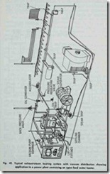
The chief difference between exhaust systems and those already described are the provisions for delivering steam from the engine to the heating system free from oil and at a constant pres sure, and for returning the condensation to the high pressure boiler (Fig. 42).
Fig. 43 shows the essential features of an exhaust-steam heating system having fractional control vacuum distribution.
The necessary devices between the engine and the inlet to the heating system are: (1) the oil separator; (2) the trap; (3) the back pressure valve; and (4) the pressure regulating valve. In addition, for mechanically producing the vacuum and returning the condensation to the high pressure boiler-an air pump, a receiver with vent, and a feed pump are required. A feed water heater should also be provided both for economy and to permit returning the condensation and make up feed water to boiler at .the proper temperature.
In operation, exhaust steam from the engine first passes through the heater, then through ,the oil separator, which frees it from the lubrication oil, the latter passing off into the oil trap. The steam now enters the heating system at (A), its pressure being prevented from rising above a predetermined limit by the back pressure valve (regulated by weight (B)) and maintained at a pre determined constant pressure by the pressure regulating valve (adjusted by weight (C) ).
The pressure regulating valve is, in fact, an automatic steam “make up” valve which admits live steam to the heating system when the exhaust is not adequate to supply the demand, thus, “making up” for this deficiency and maintaining the pressure constant.
The condensation and air removed from the system at (D) by a wet pump (as distinguished from a dry pump which removes only the air). The condensation and air are discharged into a receiver where the air passes off through a vent, the condensation being pumped by a feed pump back into the boiler after passing through a feed water heater
There is a continued loss of water through various leaks, the feed pump inlet (alleged suction) is connected at (E) (Fig. 43), with the supply from the street main or other source the amount entering the system being controlled by the “make up” valve.
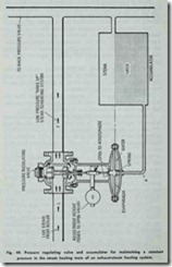
The construction of a typical regulating valve and its con nections are shown in Fig. 44. The valve is controlled by means of a governing pipe (A) (Fig. 44) connecting the diaphragm cham ber to the accumulator, the latter being connected to the heating main at the point from which the pressure regulator is to be governed.
The accumulator is always half full of water and its elevation must be such that the water line in the accumulator is level with the diaphragm, so that there will not be an unbalanced column of water to exert pressure on ·the diaphragm.
The water is provided to protect the diaphragm from the steam, the pressure of the water being transmitted from the sur face of ·the water in the accumulator to the diaphragm.
The working principle of the regulating valve and its connected devices is relatively simple. In operation, when the exhaust side (F) is at ·the predetermined pressure this brings sufficient force against the under or water side of the diaphragm to overcome the downward thrust due to the adjustable weighted level and close the valve.
If the engine slows down or there is heavy demand for heat so that the exhaust steam is not adequate to supply the demand, the pressure in the exhaust side (F) (Fig. 44) will fall and the down ward thrust of the adjustment weight will overcome the opposing pressure of the water on the diaphragm and open the valve, admi·t ting live steam from the boiler side (L) into the exhaust side (F) in sufficient quantity -to restore the pressure.
The inertia of the water in the accumulator acts as a damper to prevent over sensitiveness of the valve or hunting (i.e. the be havior of any mechanism which runs unsteadily oscillating either too far or ·too little in an attempt to adjust itself to momentary fluctuations of pressure or other conditions which cause this action).
The spring under the diaphragm acts to balance the downward thrust of the lever and hold the valve in closed position when the pressure is ·the same on both sides of the diaphragm.
The back pressure valve is used to prevent exhaust pressure exceeding a predetermined limit. This is virtually a lever safety valve designed to work at very low pressure. Some back pressure valves are so light ,that they will open or close with a variation of only two ounces. The position of the weight on the lever which is fulcrummed at (F) (Fig. 45) determines the exhaust pressure at which the valve will open .

![Fig.--43.--Exhaust--steam-heating--s[2] Fig.--43.--Exhaust--steam-heating--s[2]](http://machineryequipmentonline.com/hvac-machinery/wp-content/uploads/2020/04/Fig.-43.-Exhaust-steam-heating-s2_thumb.jpg)

![Fig.-45.-Details-of-exhauststeam-hea[2] Fig.-45.-Details-of-exhauststeam-hea[2]](http://machineryequipmentonline.com/hvac-machinery/wp-content/uploads/2020/04/Fig.-45.-Details-of-exhauststeam-hea2_thumb.jpg)