Packaged Units: Electric Air Conditioning and Gas Heating
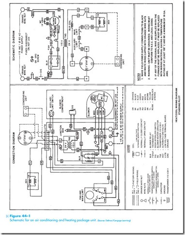
The schematic shown in Figure 44–1 is for a unit that contains both electric air conditioning and gas heating in the same package. This drawing shows both a connection diagram and a schematic diagram of this unit.
This diagram shows mainly the heating and blower controls. At the bottom of the schematic dia- gram is a component labeled condensing unit. This is the only reference to the air conditioning compressor and condenser fan on this schematic. This is not uncommon for a packaged unit.
THE COOLING CYCLE
The thermostat shows four terminal connections. The terminal labeled R is connected to one side of the 24-volt control transformer. When the thermostat is in the cooling position, an increase in temperature
will cause terminal R to make connection with terminals G and Y. When power is applied to terminal Y, a circuit is completed to the condensing unit. The other side of the condensing unit is connected to terminal C, which completes the circuit back to the control transformer. This starts the air conditioning compressor and condenser fan.
Terminal G of the thermostat is connected to the blower relay coil (BLR). When BLR coil energizes, both BLR contacts change position. The normally closed contact opens and prevents the possibility that power can be applied to the low-speed terminal of the blower fan motor. The normally open contact closes and connects power to the high-speed terminal of the motor. Notice that the indoor blower fan operates in the high-speed position when the air conditioning unit is started.
