THE FULL SYSTEM SCHEMATIC
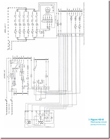
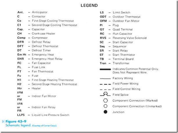
A schematic for a residential, heat-pump unit is shown in Figure 43–8. The legend for the schematic is shown in Figure 43–9. Notice in Figure 43–8 that the schematic is divided into three main sections. One section shows the outdoor compressor controls. The second section shows the indoor resistance heat and blower-fan controls, and the third section shows the low-voltage controls.
To begin the study of this control system, locate the low-voltage section of the schematic. It is divided into three sections. One section is located directly below the blower fan motor. Notice the 24-volt transformer used to provide needed power. Now locate the terminal board directly to the left of the control transformer. The terminal board shows terminal connections marked inside hexagon-shaped figures. Starting at the top and going down they are R, G, O, Y, and so on. Now locate the second control section directly under the outdoor unit schematic.
Notice the terminal board contains some of the same letter connection points as the other terminal board. Now locate the thermostat. Notice the thermostat contains terminal markings that are the same as the other two boards. These terminal markings are used to aid in tracing the circuit. For example, locate the terminal marked Y on the thermostat. Now, locate the terminal marked Y on the board closest to the control transformer. Finally, locate the terminal marked Y on the terminal board located under the outdoor unit. If the wires are traced, it will
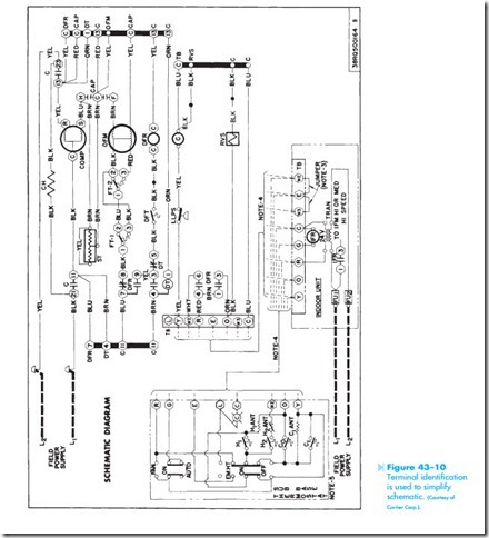
be seen that all of the terminals marked Y are connected together. This is true for all the other terminals that are marked with the same letter. Terminal markings are often used to help simplify a schematic by removing some to the connecting wires. The circuit shown in Figure 43–10 is very similar to the schematic in Figure 43–8 except that the terminal markings are used instead of connecting wires.
Notice the use of the two-stage thermostat in the schematic shown in Figure 43–8. The thermostat is so constructed that contact H1 will close before H2. Also, contact CO will close before C1. Also notice that the thermostat has an emergency heat position that permits the switch to override the thermostat and the electric resistance heaters to be connected in the circuit on a call for heat. Notice also that
this control uses an outdoor thermostat (ODT). The ODT senses the outside temperature and permits sequence relays 1 and 2 to operate only if the out- side temperature is below a certain level.
Locate the three sequence relay coils, SEQ1, SEQ2, and SEQ3. Trace the operation of the circuit when sequence relay 1 is energized. The two SEQ1 contacts located in the resistance heat section close and connect the heating elements to the line. A third SEQ1 contact is connected in series with SEQ2 timer. When this contact closes, SEQ2 timer can begin operation provided the outdoor thermostat is closed. When this timer completes its time sequence, all SEQ2 contacts close. The two SEQ2 contacts located in the resistance heat section connect the second bank of resistance heaters to the line. The third SEQ2 contact permits current to flow to SEQ3 timer. At the end of its time cycle, the two SEQ3 contacts located in the resistance heater section close and connect the third bank of heaters to the line.
Locate the blower fan motor. Notice that this is a multispeed fan motor. Only two of the speeds are used, however. High speed is used when the fan con- trol relay is energized by the thermostat. Notice that when the normally open FR contacts close, high speed is connected to the line. Also notice that the normally closed FR contacts are connected to the first SEQ1 contact. When SEQ1 contact closes, the second fan speed is connected to the line.
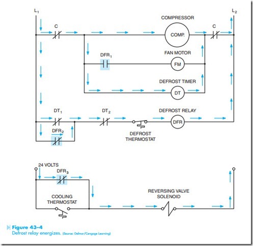
Now locate the defrost timer and defrost relay. Trace the action of the circuit as described earlier in this unit. Notice that the DFR contact located between
terminals 4 and 6 is used to override the outdoor thermostat. This permits the resistance heaters to be used during the defrost cycle, preventing cold air from being blown in the living areas during the time the unit is operating as an air conditioner.
Now locate the two outside fan-speed control thermostats labeled FT1 and FT2. Notice that when FT1 is in the position shown it permits FT2 to operate the fan in either high speed or low speed. When FT1 changes position and makes connection between terminals 1 and 3, it connects the fan in the high-speed position and FT2 has no control over the speed.
