Valves
Some authorities regard a valve as simply another type of pipe fit- ting and distinguish it from others by its capacity to control the flow of steam or hot water through the pipe. Be that as it may, the subject of valves is so extensive that it warrants a chapter of its own (see Chapter 9 of Volume 2, V“ Pipe Threads alves and Valve Installation).
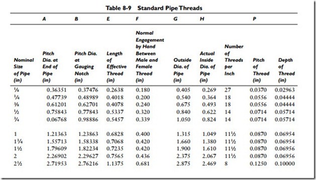
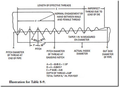
The threads used on pipes are referred to as pipe threads. The dis- tinguishing characteristic of pipe threads is that they are tapered. This results in a greater number of turns when screwing the pipe to another length of pipe or pipe fitting. When properly done, this will result in a tight, leak-free joint. Care must be taken, however, not to exceed the elastic limit or the joint will leak.
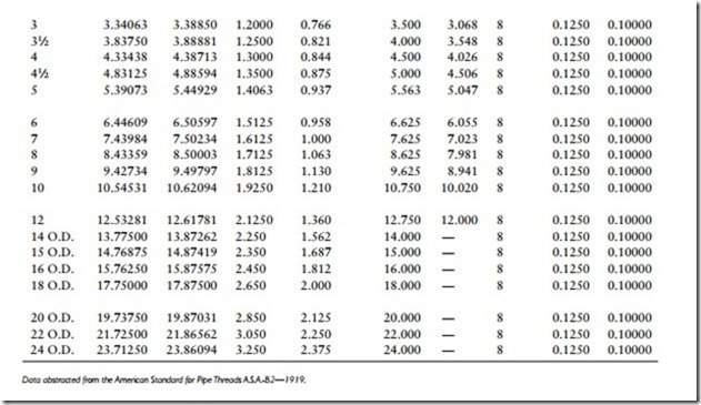
The total taper used on pipe threads in 3⁄4 inch per foot. The total number of threads per inch will vary from 27 threads for 1⁄8-in pipe to 8 threads for 21⁄2-in pipe and larger sizes. Standard pipe threads are listed in Table 8-9.
Pipe Sizing
Pipe sizing refers to the procedure of determining the projected capacities of a piping installation and selecting the pipe sizes most capable of meeting these capacities. Most methods used for deter- mining pipe sizes are only approximate calculations, and they should be considered as such when you are using them.
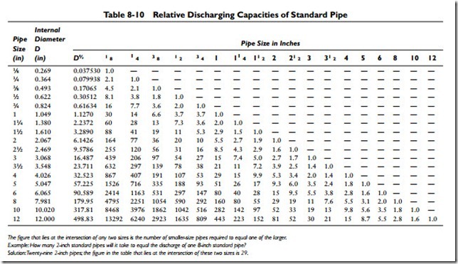
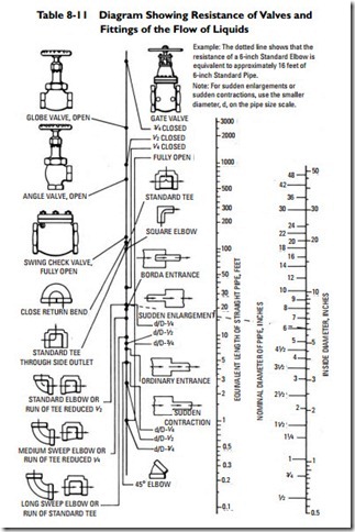
Both the American Society of Heating, Refrigerating, and Air- Conditioning Engineers (ASHRAE) and the Institute of Boiler and Radiator Manufacturers (IBR) issue publications that contain considerable data for designing the piping arrangements of various steam Pipes, Pipe Fittings, and Piping Details and hot-water space heating systems. Manufacturers of proprietary heating systems, pipes, pipe fittings, and valves also provide data for sizing pipes and valves. Examples of these data are illustrated in Tables 8-10 and 8-11. Methods for pipe sizing are explained in detail with accompanying examples. These publications can be obtained by writing to these organizations. Their addresses are given elsewhere in this book. Sometimes copies are also available at a local library.
Because pipe sizing is specific to the piping arrangement and other variables within a system, no attempt is made in this chapter to cover the subject with the detail it requires. The basic principles of the methods used for sizing steam and hot-water heating pipes, along with recommendations for their application, are described in the sections that follow.
Sizing Steam Pipes
Many manufacturers of proprietary or patented steam heating systems provide their own pipe-sizing schedules. For nonproprietary systems, the projected capacities of the piping installation must be determined by a number of sizing calculations.
The principal factors used in determining pipe sizes for a given load of steam in a heating system are the following:
• Initial pressure
• Total pressure drop allowed between the boiler and the end of the return line
• Equivalent length of run from the boiler to the farthest radia- tor or convector
• Pressure drop per 100 feet of equivalent length The total pressure drop should not exceed the initial gauge pressure of the system. As a general rule, it should not exceed 50 per- cent of the initial gauge pressure.
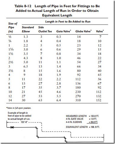
The equivalent length of run equals the actual measured length of pipe plus the equivalent straight pipe length of the fittings and valves. Table 8-12 lists equivalent lengths of the more common fittings and valves and is an example of the data provided by the ASHRAE for sizing pipes.
The pressure drop in pounds per square inch per 100 feet is determined by dividing 50 percent of the initial pressure by the equivalent length of the longest piping circuit.
For the sake of illustration, assume that you must calculate the pressure drop and determine the pipe size for a steam heating
system in which the initial pressure is 2 psig. In order to do this, the following steps are necessary:
1. Measure the length of the longest run of pipe. For our prob- lem, use the figure 500 feet.
2. Determine the assumed equivalent length. This will not exceed twice the measured length (that is, 1000 feet).
3. Determine the pressure drop for the equivalent length of pipe (50 percent of the initial pressure, or 1 psig).
4. Determine the pressure drop per 100 feet of the equivalent length of pipe:
 6. Check the pressure drop by calculating the equivalent length of run of the longest circuit from the pipe sizes determined. The pipe size determined in step 5 will be correct if the calculated pressure drop is less than the assumed pressure drop.
A steam supply main should not pitch less than 1⁄4 inch per 10 feet of run, and its diameter should not be smaller than 2 inches. In gravity one-pipe systems, the diameter of the supply main at the farthest point should not be smaller than 50 percent of its largest diameter.
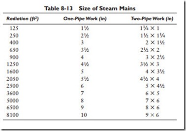
A rule-of-thumb method for determining the size of steam mains is to take the total amount of direct radiation and add to it 25 per- cent of the total for the piping allowance. Next, find the square root of this total and divide by 10. The result will be the size steam main to use for a one-pipe system. For a two-pipe system, one size smaller is generally sufficient for the supply main, and the return can be one or two sizes smaller than the supply main. A steam main should not decrease in size according to the area of its branches but much more gradually.
The aforementioned method for sizing steam mains can be illus- trated by using a structure with an assumed direct radiation of 500 square feet. Adding 25 percent for piping allowance gives 625. The square root of 625 is 25, which divided by 10 gives 21⁄2, or the size of the steam main (21⁄2 inches). For reference and practical use, refer to Table 8-13 when making calculations.
The pitch of runouts to risers and radiators should be at least 1⁄2 inch per foot toward the main. Runouts over 8 feet in length but with less than 1⁄2-inch pitch per foot should be one size larger than specified in the pipe-sizing tables.
Related posts:
Incoming search terms:
- Piping Fittings and Valves mail
- equivalent length steam pipe fittings
- equivalent length of pipe fittings and valves table
- inch of pipes and fittings
- pipe equivalent lengths
- resistance of valves and fittings to flow of fluids
- Valves Fittings and Piping Details The various items of equipment in the production facility are connected by valves fittings and piping to enable and control flow from one piece of equipment to another Chapter 9 of Volume 1 discusses factors governing th
- Valves in pipe fitting and their names
