Water-Tempering Valves
Water-tempering valves are used in hot-water space heating systems where it is necessary to supply a domestic hot-water supply at temperatures considerably lower than those of the water in the supply mains. The water-tempering valve automatically mixes hot and cold water to a desired temperature, thus preventing scalding at the fixtures. These valves are designed for use with hot-water space heating boilers equipped with tankless heaters, boiler coils, or high- temperature water heaters.
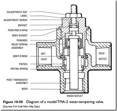
The A.W. Cash Type TMA-2 valve illustrated in Figure 10-50 is a thermostatic water-tempering valve that is shipped from the factory preset to operate at 140F° . These valves can also be field- adjusted to change the temperature of the mixed water leaving the valve by loosening the adjustment nut and turning the adjustment screw either clockwise (for colder water) or counterclockwise (for hotter water).
If turning the adjustment screw does not produce the desired mixed-water temperature, carefully touch the hot-water inlet on the valve to make sure hot water is being delivered. If you are certain hot water is getting into the valve and a temperature adjustment still fails to produce the desired results, the problem most likely lies inside the valve. Problems with these valves can usually be caused by one of the following:
• Binding of bonnet to push-rod
• Sticking of push-rod to O-ring
• Binding of piston
• Sticking of body O-ring
Before attempting to service or repair these valves, close off the hot, cold, and mixed water connections. Water must not be allowed to enter the valve when the bonnet has been removed.
Access to the internal parts of the hot-water tempering valve illustrated in Figure 10-50 is gained by unscrewing the bonnet (i.e., turning it counterclockwise) and removing it. If the bonnet is binding to the push-rod, pull the push-rod out of the bonnet and wipe it off with a crocus cloth. Do the same with the inside of the bonnet. If the push-rod O-ring is sticking, it should be removed and replaced. Reassembly is in reverse order; place the pushrod O-ring, reinsert the push-rod, and then screw the bonnet back on.
A binding piston should be removed, cleaned (with a crocus cloth), and lubricated. Access to the piston is also gained by unscrewing the bonnet. A body O-ring that is sticking should be removed and replaced. Access to the body O-ring is gained by unscrewing and removing the bonnet (leaving the push-rod in the bonnet). Push the piston and piston spring up and out through the top of the tempering valve. Lift out the post thermostat assembly. When reassembling, be sure to lubricate both the body O-ring and piston.
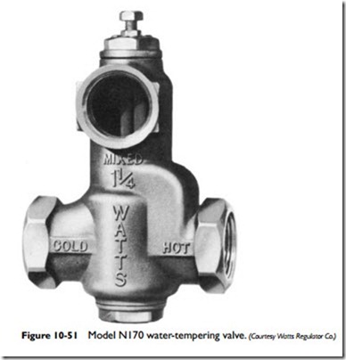
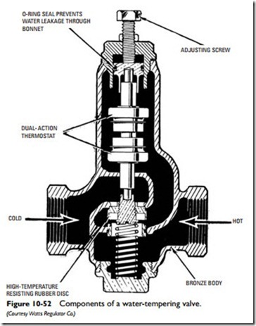
The design of the Watts No. N170 Series water-tempering valve differs from the one described above in that the discharge or mixed- water orifice is located in the bonnet (see Figures 10-51 and 10-52). The water temperature can be changed by loosening the locknut and turning the adjustment screw. Each full turn of the adjustment screw is equal to approximately a 10F° change in temperature.
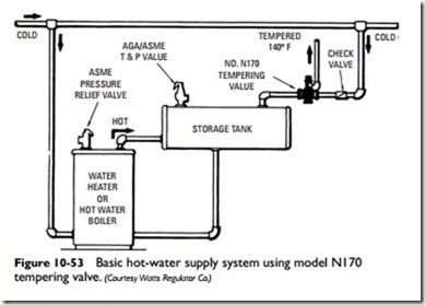
A typical installation in which a Watts No. N170 valve is used is shown in Figure 10-53. Tempered water at 140F° can be delivered to the system. The thermostat in the valve makes trapping unnecessary except in extreme cases.
A two-temperature recirculating hot-water supply system is shown in Figure 10-54. In this system, a water-tempering valve and recirculating line are used to maintain approximate fixture water temperatures of 140˚F in the mains at all times. A relatively small
capacity recirculator is used in the recirculating return piping, because very little hot water is required to maintain the low temperature in the mains. Long runs of recirculating piping should be insulated to reduce the heat loss from the piping.
Tempering valves cannot compensate for rapid pressure fluctuations in the system. Where such water pressure fluctuations are expected to occur, a pressure equalizing valve should be installed.
The Watts 70A Series tempering valve, shown in Figure 10-55, is designed for small domestic water-supply systems and tankless
heater installations. Piping connections for these applications are shown in Figure 10-56. A balancing valve should be installed below the tempering valve in the cold-water line to compensate for the pressure drop through the heater.
This valve is available with both threaded and sweat connections. It is also available in both high- (120160F) and low- (100130F) temperature models. Temperature changes are made by turning the dial-type adjustment cap on the valve (see Figure 10-57).
The Spirax Sarco Type MB water blender (see Figure 10-58) has a 55F° adjustment range for supplying tempered water to a system. It is a three-way double-ported balancing valve, essentially resembling the Watts and A.W. Cash valves in construction, except for an extended bonnet containing spirals. This type of construction allows a certain degree of pressure fluctuation between the hot- and cold-water inlets without disturbing the control of the tempered water.


