CHIMNEYS
The chimney used with an oil-fired furnace should be of suf ficient height and large enough in its cross-sectional area to meet the requirements of the furnace. The chimney area should be at least 20% greater than the area of the flue outlet. To insure the adequate removal of flue gases, the height and size of the chimney must be sufficient to create 0.02 to 0.04 inches wg draft over the fire for inputs up to 2.0 gph. For higher inputs, 0.06 to 0.08 wg is recommended. If the stack height is limited, it may be necessary to apply mechanically induced draft to the installation.
Ideally, only the furnace should be connected to the chimney.
Read the section CHIMNEYS in Chapter 11 (GAS-FIRED FUR NACES) for additional information.
Chimney Troubleshooting
Read the section CHIMNEY TROUBLESHOOTING in Chap ter 11 (GAS-FIRED FURNACES) for a description of common chimney problems and suggested remedies. The chimneys used with oil-fired furnaces are essentially identical to those used with gas-fired furnaces.
1. Blower and motor,
2. Air filter(s).
Each of these components is described in the sections that fol low. Additional information is contained in Chapter 10 (FUR NACE FUNDAMENTALS) and the various chapters in which fur nace controls and fuel burning equipment are described.
AUTOMATIC CONTROLS
The automatic controls for an oil-fired furnace can be divided into the following three principal categories:
1. Room thermostat,
2. Fan and limit control,
3. Primary control.
The thermostat and limit controls are essentially identical to those used with gas-fired furnaces. The thermostat controls the fur nace operation by signalling the primary control to turn the burner on and off in response to temperature changes in the space or spaces being heated. The fan and limit control is designed to gov ern the operation of the furnace within a specified temperature range.
Until comparatively recently, the primary control consisted of the oil burner relay and a stack switch to shut off the oil flow to the burner if the oil failed to ignite o.r the flame went out. Stack switches have largely been replaced by burner-mounted cadmium detection cells.
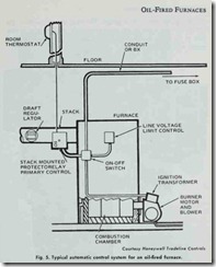
A typical automatic control system for an oil-fired furnace is
shown in Fig. 5. Additional and more detailed information about the various types of controls can be found in Chapter 4 (THER MOSTATS AND HUMIDISTATS), Chapter 5 (GAS AND OIL CONTROLS), and Chapter 6 of Volume 2 (OTHER AUTO MATIC CONTROLS).
COMBUSTION CHAMBER
The combustion chamber is that portion of the furnace which surrounds the oil burner flame and within which the combustion process takes place.
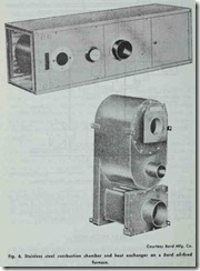
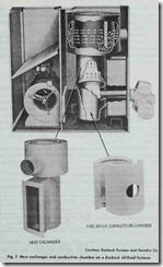
The typical combustion chamber is made of stainless steel or some sort of refractory material such as firebrick (Figs. 6 and 7). Round combustion chambers are probably the most common, al though square, rectangular, and other shapes do occur.
HEAT EXCHANGER
The heat exchanger is a device used to transfer the heat of the combustion process to the air being circulated through the ducts of the heating system. The heat exchanger is generally constructed of heavy gauge steel (14-16 gauge). The wrap around radiator type heat exchanger is one of the most commonly used designs. It con sists of an upper and lower chamber, each with an extension or pouch which must be aligned when assembled.
OIL BURNER
An oil burner is a mechanical device used to combine fuel oil with the proper amount of air for combustion and deliver it to the point of ignition. Oil burners are described in considerable detail in Chapter 1, Volume 2 (OIL BURNERS).
When installing the burner nozzle, make sure that the proper size nozzle for the installation has been selected. Electrodes are adjusted at the time of manufacture, but they should be checked when the unit is installed to make sure they are set to the burner manufacturer’s specifications.
FUEL PUMPS AND FUEL UNITS
Almost all oil burners used in residential heating installations are equipped with fuel units. It is very important to distinguish be tween a fuel unit and a fuel pump , because the two are not identi cal. A fuel unit is an oil pumping device which consists of a pump, a pressure regulating valve, and a filter. A ‘pump, on the other hand , is only an oil pumping device. A pressure regulating valve and a filter can be attached to the mountings on the pump if so desired. Fuel pumps and fuel units are described in Chapter 1, Volume 2 (OIL BURNERS). .
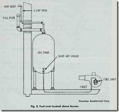
Manufacturers produce single-stage and two-stage pumps. The single-stage pumps are recommended for installations where the fuel tank is located at a level above the burner (Fig. 8). Two-stage
Table 4. Types of pumps recommended for different vacuums.
|
Total Vacuum |
Type of Pump |
|
‘Up to 3 inches vacuum |
Single-stage pump |
|
4-13 inches vacuum |
Two-stage pump |
|
14 i nch es vacuum or more |
Single-stage pump for the burner and a separate lift pump with a reservoir. |
Courtesy National Fuel Oil Institute
pumps are used in installations with underground tanks where the combination of lift, horizontal run, fittings and filters does not ex ceed the manufacturer’s rating in inches of vacuum.
The capacity of the integral pump on an oil burner should be sufficient to handle the total vacuum in the system. The vacuum is expressed in inches, and can be determined by the following procedure:
1. One inch of vacuum for each one foot of Jift .
2. One inch of vacuum for each 90° elbow in either the suc tion or return lines.
3. One inch of vacuum for each ten feet of horizontal run (:Ys inch OD line).
4. One inch of vacuum for each twenty feet of horizontal run (lh inch OD line).
After you have calculated the total vacuum, you can use this data to select the most suitable pump for the burner. Table 4 lists various vacuums and suggests appropriate pump capacities.
TROUBLESHOOTING FUEL PUMPS AND FUEL UNITS
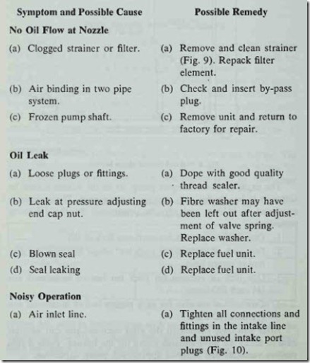
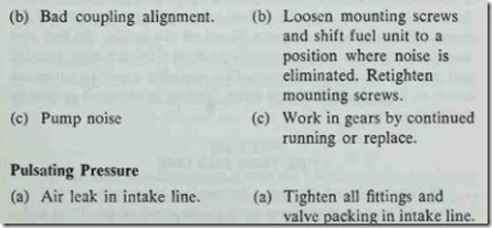
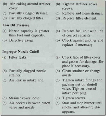
The following troubleshooting list contains the most common operating problems associated with fuel pumps and fuel units. Each problem is given in the form of a symptom, the possible cause, and a suggested remedy. The purpose of this list is to provide the op erator with a quick reference to the cause and correction of a specific problem. Much of the information used in this trouble shooting list was obtained from the “Sundstrand Technical Fuel Unit Manual,” courtesy the Sundstrand Corporation.
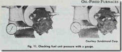
The cause of improper cutoff can be determined by inserting a pressure gauge in the nozzle port of the fuel unit (Fig. 11). Allow the fuel unit to operate for a few minutes and then shut off the burner. If the pressure drops to 0 psi on the gauge, the fuel unit should be replaced. A gauge reading above 0 psi indicates that the fuel unit is operating properly. The probable cause of improper cutoff in those cases where a gauge reading is obtained is usually air in the system.
