Oil-Fired Boilers
An oil-fired boiler contains a heat transfer surface consisting of either cast-iron sections or steel tubes, and a special combus tion chamber shaped to meet the requirements of an oil burner.
The oil burner is a device designed to mix fuel oil with air under controlled conditions and to deliver the mixture to the com bustion chamber for burning. The burner is mounted outside the chamber. The oil burners used in residential heating boilers are usually high-pressure atomizing type burners although other types are used on occasion.
It is possible to convert a coal-fired boiler to oil by redesigning the combustion chamber. However, boilers specifically designed to use oil as a fuel have proven to be more efficient and economical than coal-fired boilers converted to oil.
ACCESSORIES and HOT WATER BOILER FITTINGS AND ACCESSORIES). An exploded view of a Hydrotherm oil-fired boiler illustrates the location of the various controls and acces sories (Fig. 17).
Coal-Fired Boilers
A typical coal-fired boiler contains a grate for the fuel bed located beneath metal heat transfer surfaces (e.g. cast-iron sec tions). The hot gases resulting from combustion rise through the passages transferring their heat to the water contained in them.
The controls and accessories used to operate a coal-fired boiler are described in Chapter 3, Volume 2 (COAL FIRING METHODS). The controls and accessories used to govern the temperature, pressure, and flow rate of the heat conveying medium are described in this chapter (see STEAM BOILER FITTINGS AND ACCESSORIES and HOT WATER BOILER FITTINGS AND ACCESSORIES).
A coal-fired boiler requires more draft than gas- or oil-fired boilers because of the resistance of the fuel bed. Special care must be given to the design of the chamber surrounding the grate to insure sufficient volume for a proper mixture of fuel and air. Provisions must also be made for introducing sufficient air through the grate (and fuel bed) for the combustion process.
Before the introduction of oil burners, coal was generally used for fuel and is still largely used especially for heating plants already built and in cases where the owner cannot afford the ex pen se of converting to oil. Moreover, some types of cast-iron boiler s designed to burn coal are not suited to burn oil, which adds to the expense of a conversion job. Finally, the increasing world-wide shortage of oil will find it more and more necessary to find applications for low polluting uses of coal as a heat source. An important use for coal will be steam and hot water heating systems equipped with devices to reduce the polluting effect of burning coal.
Coal burning boilers are usually arranged for hand firing, but may be fitted for automatic stoker operation. In many automatic stokers , fuel is carried from the hopper through a feed tube by mean s of a rotating worm. Intermittent action of the worm agitates the fuel bed, prevents arching of the coal in the retort and assures that the incoming air reache s every part of the fire at all times. An auxiliary air connection between the feed tube and wind box prevents gas accumulating in the tube and eliminates any ten dency to “smoke back” through the hopper.
An underfeed stoker is one in which the fuel is fed upward from underneath. The action of a screw or worm carries the fuel back through a retort from which it passes upward, as the fuel is consumed, the ash being finally deposited on dead plates on either side of the retort from which it can be removed.
Only part of the fuel being burned is actually burned in the
fuel bed. Under the influence of high temperature created in the fuel bed and lack of sufficient air, unburned gases are released above the retort and tuyeres and unless these gases are mixed with air and burned inside of the combustion chamber, they will leave the boiler in the unburned condition, carrying a large per centage of the heat originally contained in the coal.
Nearer the outside of the fuel bed, the fuel burns less vio lently and much more air is passed through the fuel bed than is necessary. It is this excess air that must be mixed with the un burned gases issuing from the central point of the fuel bed if high combustion efficiency is to be realized.
Coke can also be used to fire boilers, but it requires different handling. In order to be completely consumed, coke needs a greater volume of air per pound of fuel than coal, and therefore requires a stronger draft, which is increased by the fact that it can only burn economically in a thick bed.
Because less coke is burned per hour per square foot of grate than coal, a larger grate and a deep fire pot are required to accomodate the thick bed of coke.
The quick flaming combustion which characterizes coal is not produced by coke because the latter fuel contains very little hydrogen; however, a coke fire is more even and regular.
Electric-Fired Boilers
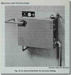
Compact electric-fired boilers enjoy widespread use in forced hot-water heating systems. A typical example of one of these boilers is shown in Fig. 18. Heat is generated by electric heating elements immersed in water contained in a waterproof castiron shell. Although small in size, these boilers are capable of gen erating as high as 90,000 Btu’s per hour; enough heat for the average 8-room house.
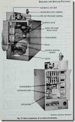
The basic components of an electric-fired boiler are shown in Fig. 19. An automatic air vent (1) located above the castironboiler shell (8) is used for bleeding off trapped air from the water system. Safety devices include a water pressure relief valve (2) for reducing system pressure; an adjustable limit control (3) which allows selection of maximum boiler water temperature for system design; and preset pressure controls (4) to guarantee safe operation within the prescribed pressure range.
The limit control is an immersion device which shuts off the boiler if the temperature exceeds a predetermined setting. The preset pressure controls consist of a high pressure switch and a preset safe-fill switch. The high pressure switch is designed to deenergize the boiler if the pressure reaches 28 psi. This switch is reinforced by the relief valve, which is preset to relieve system pressure at 30 psi. The preset safe-fill switch prevents the electric heating elements from being energized unless pressure in the sys tem is 4 psi. This prevents any chance of the heating elements
burning out should an attempt be made to operate the boiler while dry.
The circulator (5), cast-iron boiler shell (8), and expansion tank (9) are all enclosed within the outer steel jacket ( 10) of the boiler. The electric heating elements (6) are mounted inside the ends of the boiler casting. A drain valve (11) mounted below the boiler casting is designed for the connection of standard hose fittings.
All controls are prewired and mounted in place by the manu facturer. The only electrical connections that need to be made during the installation of the boiler are those to the main power supply and room thermostat.
The sequencing relay switch (7) provides for an incremental loading on the electric service line. This reduces line voltage fluc tuation and prevents power surge during energizing.
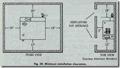
Minimum installation clearances for the boiler described above are shown in Fig. 20. Two air openings of 108 sq. in. (6″X18″) each are required for closet installation.
A typical piping arrangement for a series loop hot-water heating system using an electric-fired boiler of this capacity is shown in Fig. 21. An outline of the procedure used for filling this system is as follows:
1. Close all zone valves except zone to be purged.
2. Open boiler drain valve.
3. Open fill valve.
4. Close purge valve.
5. Vent air from boiler by manually opening relief valve.
6. Open second valve to be purged, and close first zone.
7. After second zone is purged, open third zone valve and close second zone.
8. Repeat the procedures described in Steps 6 and 7 for as many zones as in the system.
9. When all zones have been purged, close boiler drain cock.
10. When water appears at relief valve, release lever and allow to close.
11. Continue filling until pressure gauge reads approximately 12 psi. Close fill valve.
12. Open purge valves.
Where multiple circuits are used without zone valves, balan cing valves should be installed for balancing. These can be shut off to purge each circuit individually. For a single loop system, no additional vents, valves, drains or other accessories are required.
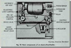
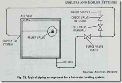
Smaller electric-fired boilers having outputs ranging from approximately 6000 to 20,000 Btu’s are available for individual apartment heating or for residential zoned heating through the use of several units. The basic components of one of these smaller boilers is shown in Fig. 22. The piping arrangement for a series loop heating system using one of these boilers is illustrated in Fig. 23. The procedure for filling the system is similar to the one outlined above except for the elimination of Steps 6-9.

