Heat Pump Defrost System
A heat pump defrost system consists of a defrost thermostat and a defrost control. The defrost thermostat is located on the liquid line between the expansion/check valve and the distributor. The defrost control board is located in the control box.
Defrost Thermostat
Its function is to signal the defrost control board to start the defrost timing when the defrost thermostat senses a preset low temperature. It terminates the defrost mode when the liquid line warms up to a higher preset temperature.
Defrost Control Board
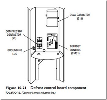
The defrost control board is located in the control box. The type and location of the various components on a defrost control board will vary among different manufacturers. The two defrost control boards shown in Figure 10-21 include a time-temperature defrost control, defrost relay, time delay, two diagnostic LEDs, a 24-volt terminal strip for field wiring connections, and provisions for pressure switch safety circuit connections. The control provides auto- matic switching from normal heating operation to defrost mode and back depending on the defrost thermostat settings.
There are two principal types of defrost controls: demand-frost controls and time-temperature defrost controls. The demand-frost controls activate the defrost mode only when frost or ice forms on the coil. The time-temperature defrost controls, on the other hand, activate the defrost mode at regular timed intervals for set periods of time whether frost or ice is present on the outdoor coils or not. In both cases, activating the defrost mode causes the reversing valve to divert warm refrigerant fluid to the outdoor coil to thaw the frost or ice forming on the unit coils.
Two LEDs are installed on the defrost board for diagnostic purposes. The LEDs flash a specific sequence according to the condition.
The time delay protects the compressor from short-cycling in case the power to the unit is interrupted or a pressure switch opens. The time delay is electrically connected between a thermostat terminal and the compressor contactor.
Other relays, connections, and components forming a part of the defrost control system and located on the defrost control board include the following:
• Defrost relay
• Pressure switch safety circuit connections
• 24-volt terminal strip connections
• Defrost interval timing pins
