Copper Tubing
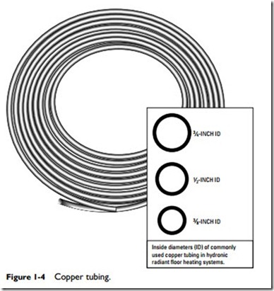
In most modern radiant floor heating systems, the water is circulated through copper or cross-linked polyethylene (PEX) tubing (see Figure 1-4). The metal coils used in hydronic radiant heating systems commonly are made of copper tubing (both the hard and soft varieties). Steel and wrought-iron pipe also have been used in hydronic floor heating systems, but it is rare to find them in modern residential radiant floor heating systems.
Inside diameters (ID) of commonly used copper tubing in hydronic radiant floor heating systems.
The soft tempered Type L copper tubing is recommended for hydronic radiant heating panels. Because of the relative ease with which soft copper tubes can be bent and shaped, they are especially well adapted for making connections around furnaces, boilers, oil- burning equipment, and other obstructions. This high workability characteristic of copper tubing also results in reduced installation time and lower installation costs. Copper tubing is produced in diameters ranging from 1⁄8 inch to 10 inches and in a variety of different wall thicknesses. Both copper and brass fittings are available. Hydronic heating systems use small tube sizes joined by soldering.
The size of the pipes or tubing used in these systems depends on the flow rate of the water and the friction loss in the tubing. The flow rate of the water is measured in gallons per minute (gpm), and constant friction loss is expressed in thousandths of an inch for each foot of pipe length. For a description of the various types of tubing used in hydronic heating systems, see the appropriate sec- tions of Chapter 8 (“Pipes, Pipe Fittings, and Piping Details”) in Volume 2.
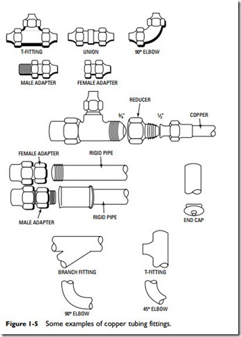
Most of the fittings used in hydronic radiant heating systems are typical plumbing fittings. They include couplings (standard, slip, and reducing couplings), elbows (both 45° and 90° elbows), male and female adapters, unions, and tees (full size and reducing tees) (see Figure 1-5).
Three special fittings used in hydronic radiant heating systems are the brass adapters, the brass couplings, and the repair couplings. A brass adapter is a fitting used to join the end of a length of 3⁄4-inch diameter copper tubing to the end of a length of plastic polyethylene tubing. A brass coupling, on the other hand, is a fitting used to join two pieces of plastic heat exchanger tubing. A repair coupling is a brass fitting enclosed in clear vinyl protective sheath to prevent concrete from corroding the metal fitting. The fitting is strengthened by double-clamping it with stainless steel hose clamps.
A decoiler bending device or jig should be used to bend metal tubing into the desired coil pattern. Only soft copper tubing can be easily bent by hand. It is recommended that a tube bender of this type be made for each of the different center-to-center spacing needed for the various panel coils in the installation.
Soft copper tubing is commonly available in coil lengths of 40 feet, 60 feet, and 100 feet. When the tubing is uncoiled, it should be straightened in the trough of a straightener jig. For convenience of handling, the straightener should not be more than 10 feet long.
Note
Most copper tubing leaks will occur at bends or U-turns in the floor loops.These leaks are caused by water or fluids under high pressure flowing through the weakened sections of tubing. The weakened metal is commonly caused by improper bending techniques.
Whenever possible, continuous lengths of tubing should be used with as few fitting connections as possible. Coils of 60 feet or 100 feet
are best for this purpose and are generally preferred for floor panels. The spacing between the tubing should be uniform and restricted to 12 inches or less. Use soldered joints to make connections between sections of tubing or pipe.
Cross-Linked Polyethylene (PEX) Tubing
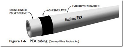
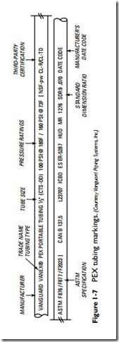
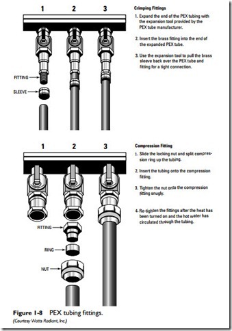
Cross-linked polyethylene (PEX) tubing is commonly used indoors in hydronic radiant heating panels or outdoors embedded beneath the surface of driveways, sidewalks, and patios to melt snow and ice. It is made of a high-density polyethylene plastic that has been subjected to a cross-linking process (see Figures 1-6, 1-7, and 1-8). It is flexible, durable, and easy to install. There are two types of PEX tubing:
• Oxygen barrier tubing
• Nonbarrier tubing
Oxygen barrier tubing (BPEX) is treated with an oxygen barrier coating to prevent oxygen from passing through the tubing wall and contaminating the water in the system. It is designed specifically to prevent corrosion to any ferrous fittings or valves in the piping system. BPEX tubing is recommended for use in a hydronic radiant heating system.
Nonbarrier tubing should be used in a hydronic radiant heating system only if it can be isolated from the ferrous components by a corrosion-resistant heat exchanger, or if only corrosion-resistant system components (boiler, valves, and fittings) are used.
PEX tubing is easy to install. Its flexibility allows the installer to bend it around obstructions and into narrow spaces. A rigid plastic cutter tool, or a copper tubing cutter equipped with a plastic cut- ting wheel, should be used to cut and install PEX tubing. Both tools produce a square cut without burrs.
PEX tubing can be returned to its original shape after accidental crimping or kinking by heating it to about 250–275°F. This attribute of PEX tubing makes it possible to perform field repairs without removing the damaged tubing section. This is not the case with poly- butylene tubing, which is not cross-linked. Synthetic rubber tubing
is also not cross-linked, but its material composition and its flexibility make it very resistant to crimping or kinking damage.
Manifolds
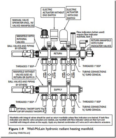
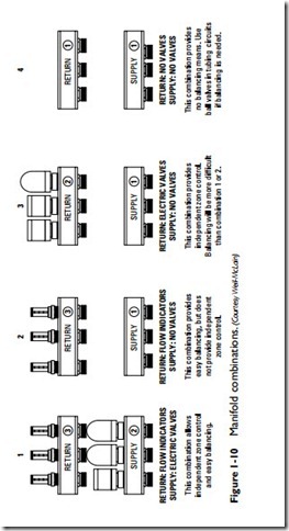
A manifold is a device used to connect multiple tubing lines to a single supply or return line in a hydronic radiant floor heating system (see Figures 1-9 and 1-10). Each heating system has at least two
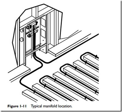
types of manifolds: a supply manifold and a return manifold. A sup- ply manifold receives water from the heating appliance (that is, the boiler, water heater, or heat pump) through a single supply pipe and then distributes it through a number of different tubing lines to the room or space being heated (see Figure 1-11). A return manifold provides the opposite function. It receives the return water from the room or space through as many tubing lines and sends it back to the boiler by a single return pipe. A supply manifold and a return manifold are sometimes referred to jointly as a manifold station.
Preassembled manifolds are available from manufacturers for installation in most types of heating systems. Customized manifolds can also be ordered, but they are more expensive than the standard, preassembled types.
A supply manifold, when operating in conjunction with zone valves, can be used to control the hot water flow to the distribution lines in the radiant heating system. The zone valves, which are usually ball valves, can be manually adjusted or automatically opened
and closed with a zone valve actuator. Some zone valves are designed as fully open or fully closed valves. Others are operated by a modulating actuator that can adjust the opening to the heat required by the zoned space.
A supply manifold with zoning capabilities is sometimes called a zone manifold or distribution manifold. In addition to zone valves, these manifolds also can be ordered to include supply and return water sensors, the circulator, and a control panel with indoor and outdoor sensors.
Depending on the heating system requirements, a manifold may also include inline thermometers or a temperature gauge to measure the temperature of the water flowing through the tubing; check valves or isolation valves to isolate the manifold so that it can be serviced or repaired; drain valves to remove water from the manifold; an air vent to purge air from the system; and pump flanges (for the circulator) plus all the required plumbing connections and hardware.
Manifold balancing valves regulate each zone (loop) to ensure efficient heat distribution and eliminate those annoying cold and hot spots on the floor. These valves can be adjusted to deliver the design flow rate of water in gallons per minute (gpm). Some manifolds are designed to electronically read the flow and temperature of the water in individual tubing loops. This function results in rapid and accurate data feedback for balancing. It also makes troubleshooting problems easier.
Manifolds are available for mounting on walls or installation in concrete slabs. The latter type, sometimes called a slab manifold, is made of copper and is available with up to six supply and six return loop connections. Slab manifolds also should be equipped with a pressure-testing feature so that they can be tested for leaks before the slab is poured.
Slab manifolds are installed with a box or form that shields the device from the concrete when it is poured. All connections remain below the level of the floor except for the tops of the supply and return tubing.
Valves and Related Control Devices
Valves and similar control devices are used for a variety of different purposes in a hydronic radiant floor heating system. Some are used as high-limit controls to prevent excessively hot water from flowing through the floor loops. Some are used to isolate system components, such as the circulating pump, so that it can be serviced or removed without having to shut down the entire system. Others are used to regulate the pressure or temperature of the water, to reduce the pressure of the water before it enters the boiler, or to regulate the flow of water.
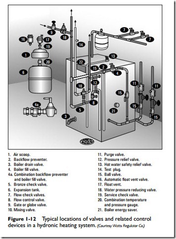
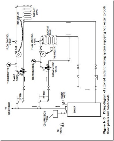
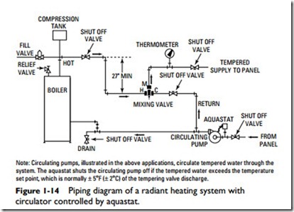
Many of the different types of valves and control devices used in hydraulic radiant floor heating systems are listed in the sidebar. A brief description of the more commonly used ones is provided in this sec- tion. For a fuller, more detailed description of their operation, mainte- nance, service, and repair, read the appropriate sections of Chapter 9 (“Valves and Valve Installation”) of Volume 2. Not all the valves listed in the sidebar or the ones described in this chapter will necessarily be used in the same heating system. The valves chosen will fit the require- ments of a specific application (see Figures 1-12, 1-13, and 1-14).
Aquastat
An aquastat is a control device consisting of a sensing bulb, a diaphragm, and a switch (see Figure 1-14). As the temperature sur- rounding the sensing bulb increases, the gas inside the bulb expands and flows into the diaphragm. This action causes the diaphragm to expand and activate the switch controlling the con- nected device. When temperatures exceed the high-limit setting on
the aquastat, it shuts off the circulator or circulators until the problem can be corrected.
The switching contacts of some aquastats can be manually adjusted for temperature settings. In other systems, the switching contacts of an aquastat may be preset at a predetermined temperature setting.
Backflow Preventer
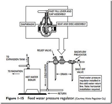
A backflow preventer is a valve used to prevent the mixing of boiler hot water with domestic (potable) water (see Figure 1-15). Most systems use an inline backflow preventer. It must be installed with the arrow on the side of the valve facing the direction of water flow. Sometimes a backflow preventer and boiler fill valve are combined in the same unit.
Ball Valve, Gate, and Globe Valves
A ball valve can be used to isolate components or lines, or to regu- late flow. A gate valve is often used to isolate components for ser- vice, repair, or replacement. They are not designed to regulate the flow of water. A globe valve is used to regulate the flow of water in a radiant heating system.
Note
Use a fully closing ball or gate valve on the supply and return line so that the manifold can be isolated and serviced without interrupting the pressure in the rest of the system.
Boiler Drain Valve
A boiler drain valve is a quarter-turn ball valve used to drain water from a boiler. As shown in Figure 1-12, it is located near the bot- tom of the boiler close to a floor drain.
Check Valves
A check valve (also called a shutoff valve) is used to ensure that water is flowing in the correct direction by providing positive shut- off to the flow. Typical locations of check (shutoff) valves are shown in Figures 1-12, 1-13, and 1-14.
A swing check valve is designed to prevent the backflow of water. A flow-control valve is a check valve used to prevent circulation of the hot water through the heating system when the thermostat has not called for circulation. The flow-control check valve must be used when the radiant panels are located below the boiler.
Note
Flow-control valves should not be used when the radiant floor panel is below the level of the boiler.
Another type of check valve used in a radiant floor heating sys- tem is the isolation valve (also sometimes called a service valve).
The isolation valve is used to isolate a hydronic system component for servicing and/or removal so that it can be repaired or replaced. Isolating the component eliminates the need to drain and refill the system with water.
Caution
Reduce the system pressure to a safe level before attempting to remove system components.
Caution
An isolation valve is not designed to isolate a pressure (safety) relief valve or other safety or flow-sensitive components.
Feed Water Pressure Regulators
A feed water pressure regulator is used to fill both the boiler and system piping (including the floor panel loops) with water. A typi- cal location of a feed water pressure regulator in the cold-water return line is illustrated in Figure 1-15. These valves also maintain the water pressure at the required level in the system at all times. If a leak should occur in the system, the feed water pressure regulator is designed to provide the required amount of makeup water. Using the feed water pressure regulator speeds filling and purging of air from the piping during the initial fill procedure.
Disconnect Switch
Two principal types of on-off switches are used to open or close an electrical circuit: the disconnect switch and the thermostat (see Thermostat in this section).
The disconnect switch is a manually operated on-off switch used to shut down the entire heating system when a problem is begin- ning to develop. When the switch is in the off position, the circuit opens and the electricity operating the boiler, heat pump, or water heater is shut off. When it is in the on position, the circuit closes (that is, completes itself) and electricity bypasses the boiler, heat pump, or space-heating water heater.
Inline Thermometer
An inline thermometer is a device that is used to monitor the water temperature as it circulates through the system. Two inline thermome- ters are installed in the heating system. One monitors the temperature of the water as it enters the supply line. The other monitors the tem- perature of the water as it leaves. The difference between these two measurements provides clues to the operating efficiency of the system.
Mixing Valve
A thermostatic mixing valve is used in a radiant heating system to recirculate a variable portion of the return water and at the same
time add a sufficient quantity of hot boiler water to maintain the required water temperature in the loops. These valves are also called thermostatic mixing valves, water blending valves, water blenders, water tempering valves, or tempering valves. Typical locations of mixing valves are shown in Figures 1-12, 1-13, and 1-14.
Both manual and automatic modulating mixing valves are used in hydronic heating systems. The manual mixing valve is often used to control the water temperature in a high-mass concrete slab. It is not as accurate as an automatic valve (for example, a thermostatic valve), but the high-mass concrete slab stores it and releases it slowly over a long period of time, making exact temperature con- trol unnecessary.
The three-way and four-way thermostatic mixing valves provide automatic control of the mixed water temperatures. The valve varies the flow of hot water between its hot port and its cold port so that it can deliver through its mixed port a steady flow of water at a constant temperature.
Mixing valves are often used with high-temperature boilers designed to provide water at temperatures of more than 160°F.
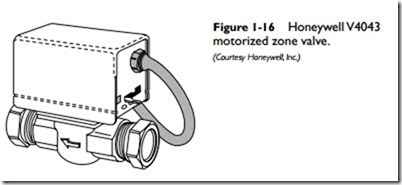
Motorized Zone Valve
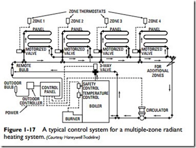
A motorized zone valve is used to control the flow of water through a single zone (see Figure 1-16). It consists of a valve body combined with an electric actuator. A radiant panel heating sys- tem will often use a number of motorized zoning valves to main- tain a uniform temperature throughout the rooms and spaces in the structure. As shown in Figure 1-17, a motorized zone valve is used to control each zone. Motorized zone valves are controlled by an aquastat, individual thermostats at each loop, or a room thermostat.
Note
A zone valve simplifies the piping required for a hydronic heating sys- tem because it eliminates the need for a flow check valve and relays.
Pressure-Reducing Valve
A pressure-reducing valve is designed to reduce the pressure of the water entering the system and to maintain the pressure at a specific minimum setting (usually about 12 lbs). A typical location of a pressure relief valve is shown in Figure 1-12.
Pressure Relief Valve
A pressure relief valve (also sometimes called a safety relief valve) is used to prevent excessive and dangerous pressure from entering the system. It is located on top of the boiler or very close to it (see Figures 1-12, 1-13, and 1-14).
Purge and Balancing Valves
Purge and balancing valves are used on either the supply or return side of the manifold in systems where multiple manifolds are served by only one circulator. Among its varied functions is (1) to allow adjustments of proper water flow for each loop; (2) to function as a shutoff valve and a drain valve for each zone or loop; (3) to control (balance) water flow through the circulation loop; and (4) to pro- vide a means of expelling air from heating zones during initial loop fill (valve is located on the boiler return piping). If the heating sys- tem contains individual loops of unequal length, each should be equipped with a balancing valve.
Circulator
The circulator (circulating pump) provides the motive force to circulate the water through the radiant heating system. Sometimes a variable-speed pump is used to maintain a supply water temperature between 90°F and 150°F.
In some zoned systems, a circulator operates in conjunction with a zone thermostat instead of a zoning valve to maintain a uniform floor temperature in each room or space of the structure. The zone thermostat controls the temperature in the zone by turning the circulator on and off. The size of the circulating pump selected for a radiant panel heating system will depend on the pressure drop in the system and the rate at which water must circulate. The circulation rate of the water is determined by the heating load and the design temperature drop of the system and is expressed in gallons per minute (gpm). This can be calculated by using the following formula:
The total heating load is calculated for the structure and is expressed in Btu per hour. A value of 20°F is generally used for the design temperature drop (T) in most hot-water radiant panel heat- ing systems. The other two values in the formula are the minutes per hour (60) and the weight (in pounds) of a gallon of water (8).
By way of example, the rate of water circulation for a structure with a total heating load of 30,000 Btu per hour may be calculated as follows:
Expansion Tank
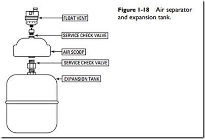
An expansion tank (also called a compression tank) is required for use in all closed hydronic radiant heating systems (see Figure 1-18). Water and other fluids expand when they are heated. The expansion tank provides space to store the increased volume to prevent stress on the system.
Air Separator
An air separator (also called an air scoop or an air eliminator) is a device used in a closed radiant heating system to capture and remove air trapped in the water (see Figure 1-18). Some of these devices are
equipped with tappings for the installation of an expansion tank and air vent.
Heat Exchanger
A heat exchanger is a device used in some radiant heating systems to separate dissimilar fluids such as water mixed with antifreeze (in snow- and ice-melting applications) and water (for radiant floor heating tubing and domestic hot water). Its function is to allow the transfer of heat between the fluids without allowing them to mix and thereby contaminate one another.
Automatic Controls
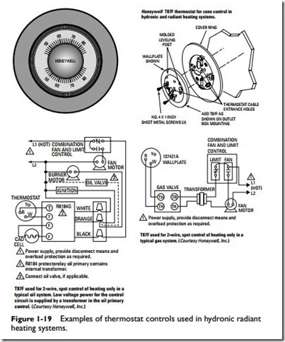
While any thermostatic method of control will function with a radiant floor heating system, the most desirable method is one based on continuously circulating hot water. The temperature of the water should be automatically adjusted to meet outdoor conditions, but the circulation itself is controlled by interior limiting thermostats instead of the simple off-on method of circulating hot water at a fixed temperature (see Figure 1-19).
Some radiant floor heating systems are designed with a thermo- stat for each zone (see Figure 1-17). A more common method is to group several rooms or spaces together and control them by a sin- gle thermostat. In this approach, the kitchen and dining room may be included in one thermostat-controlled loop, the bedrooms in another, the bathrooms in still another, and so on.
Many HVAC control manufacturers are now producing control consoles such as the one shown in Figure 1-20.
