Reversing Valve and Solenoid
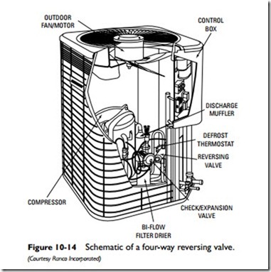
A refrigerant reversing valve with an electromechanical solenoid coil is used to reverse refrigerant flow during unit operation (see Figure 10-14). It allows the heat pump to operate in either the heating
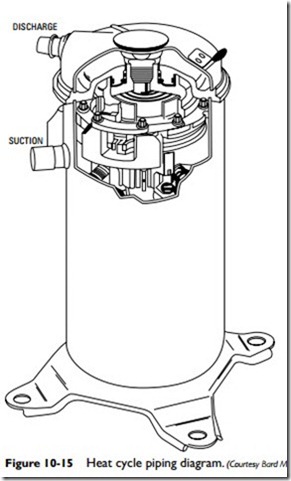
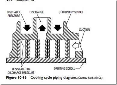
or cooling mode by changing the direction of the refrigerant between the indoor and outdoor coils. The operation of a four-way reversing valve is shown schematically in Figures 10-15 and 10-16.
Whenever the reversing valve changes the direction of refrigerant flow, it also changes the functions of the indoor and outdoor coils. During the heating mode, the indoor coil functions as an evaporator and is sometimes referred to as an evaporating coil. This is true only as long as the system is in the heating mode. If the system is in the cooling mode, the direction of the refrigerant reverses and the indoor coil becomes a condenser (that is, a condenser coil). The reversing valve also changes the function of the outdoor coil when it changes the direction of refrigerant flow.
Conventional refrigerant reversing valves cause pressure drops and undesired heat exchange that leads to a 5 to 10 percent degradation of heat pump performance. A newly designed four-way reversing valve has been developed to solve this problem.
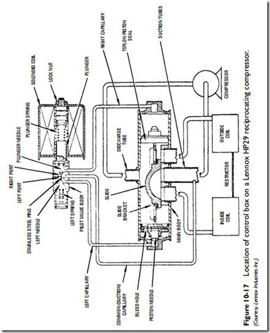
As mentioned, the four-way reversing valve is operated by a solenoid coil. When the room thermostat calls for heat, the solenoid
coil is energized. This action causes a nylon slide in the vale cylinder to move to the right and allow the high-pressure refrigerant to flow through capillary tubes to the left piston side of the main valve. The low-pressure refrigerant on the left side flows back to the compressor. When the system calls for cooling, the valve operation is reversed.
Thermostatic Expansion Valve
The thermostatic expansion valve (TXV) was developed to provide more precise control of the refrigerant flow to the indoor coil. The valve meters the exact amount of refrigerant required to
meet the indoor coil load demands. Using a thermostatic expansion valve increases the efficiency of the unit.
Note
A compressor in a system equipped with a thermostatic expansion valve may have difficulty starting. This may be caused by a delay in system pressure equalizing for a short period of time when the compressor is in the off cycle.The solution is to install a start capacitor in the control box.
Desuperheater
Some heat pumps are equipped with a unit that recycles waste heat from the interior of the structure during the cooling cycle. The recycled waste heat is used to produce domestic hot water.
Control Box
The control box contains various controls, connections, and wiring important to the operation of the heat pump. The location of a control box on a Lennox reciprocating heat pump is shown in Figure 10-17.
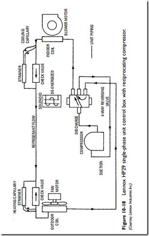
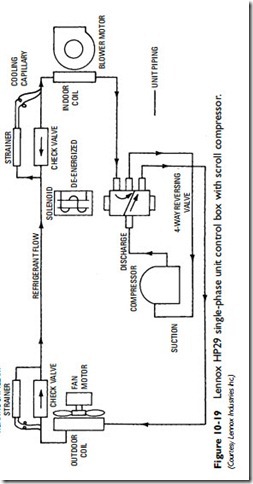
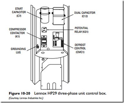
The controls may include contactors, capacitors, relays, circuit boards, transformer, and various accessories. Not all control boxes will contain the same controls, so it is important to consult the heat pump manufacturer’s service and repair manuals when repairing or replacing a control box. As shown in Figures 10-18, 10-19, and 10-20, control boxes may even differ among the makes and models of the same manufacturer.
Start, Run, and Dual Capacitors
Every control box will contain capacitors. A capacitor is an electronic device that stores a charge (energy). A start capacitor (also sometimes called a motor start capacitor) is used to provide the torque required to start the compressor motor. It does this while working in conjunction with a run capacitor (also called a motor run capacitor) or a dual capacitor. A dual capacitor gives a phase shift to single-phase motors in scroll-type or reciprocating-type compressor motors. It is called a dual capacitor because it contains one capacitor for the compressor motor and another for the fan motor.
Compressor Contactor
A contactor is an electrically operated switching device in the heat pump control circuit (commonly 24 volts AC circuits). It creates a magnetic field to pull in a set of contacts controlling another device that may or may not receive its electrical power from the same circuit.
Defrost Control
The defrost control (or defrost control board) is described later in this chapter. See Heat Pump Defrost System.
Relays
The potential relay controls the starting function of the compressor motor. The outdoor fan relay is used in some split-system heat pumps to control the operation of the fan in the outdoor unit.
Fan/Blower Motors
Both the outdoor and indoor units of a split-system heat pump are equipped with a fan. The indoor fan (or blower as it is also called) is used to blow the warm air created by the indoor coil (evaporator) through the ductwork into the rooms and spaces of the structure. The most efficient type of indoor blower is a variable-speed one because its operation enables it to compensate for potential airflow restrictions caused by dirty filters or coil or partially blocked air ducts.
Related posts:
Incoming search terms:
- heat pump compressor sensor valve
- what is the purpose of the reversing valve electrical coil
- solenoid valve used in heat pump
- Solenoid pump mail
- reversing valve solenoid coil problems
- reversing valve solenoid coil located
- Reverse valve solenoid coil monroe
- heat pump solenoid valve
- heat pump reversing solenoid
- heat pump reverse valce solenoid wiring
- what’s the color code for heat pump reversing valve solinoid
