Direct-Spark Ignition Module
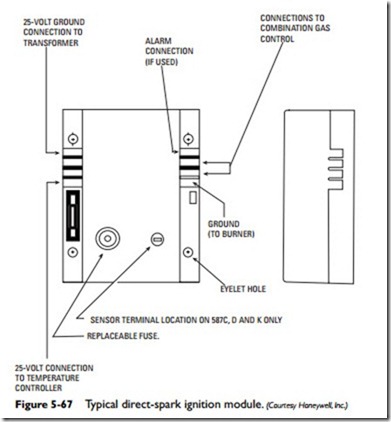
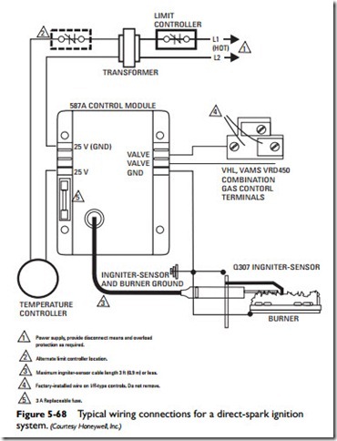
The direct-spark ignition (DSI) module illustrated in Figure 5-67 is a low-voltage, solid-state unit that controls the gas valve, monitors the burner flame, and generates a high-voltage spark for ignition. DSI modules are available with or without a purge timer and with separate or combined igniters and flame sensors. Typical wiring connections for a direct-spark ignition system are illustrated in Figure 5-68.
Hot-Surface Ignition Module
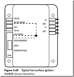
The principal components of a hot-surface ignition system are the hot-surface ignition module, a line voltage silicon carbide igniter (also sometimes called a glow stick or glow plug), a remote flame sensor, a 24-volt AC ignition-detection control, and a 24-volt (AC) redundant gas valve (see Figure 5-69). The flame sensor is designed to detect the presence of a flame. It can be mounted remotely on multiple burners or next to the gas burner.
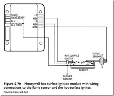
The hot-surface ignition module, similar to the one shown in Figure 5-70, is a microprocessor-based gas ignition control designed for direct ignition gas-fired appliances. It provides direct
main gas burner ignition, remote sensing, and prepurging. It will retry for ignition and has a fixed time for flame lockout.
Some hot-surface ignition modules have self-diagnostic capabili- ties. A diagnostic light on the HSI module provides the following information:
• If the diagnostic light on the module flashes on and off one time at initial startup, the unit is functioning properly.
• If the diagnostic light is lit continuously, there is most likely an internal problem with the module. Check for an internal problem by interrupting the line power or 25-volt thermo- static power for a few seconds and then restore it. If the burner still fails to ignite, replace the module.
• If the diagnostic light continues to flash, the problem is in the external components or wiring.
For HIS modules without self-diagnostic capabilities, a qualified HVAC technician or electrician should troubleshoot the system with the appropriate test equipment. The test equipment should include the following:
• A volt-ohm meter for checking both the voltage and the resistance.
• A precision microammeter for checking the flame sensor out- put and location.
• A pressure gauge (low scale) for checking gas pressure.
Warning
Extreme caution must be taken when working on a hot-surface ignition system. Because of the high voltage present, there is always the potential for serious electrical shock.
If the unit is not equipped with a self-diagnostic light, closely follow the troubleshooting suggestions provided by the manufacturer. These will be specific to the make and model. Some simple things to look for include the following:
• Checking to make certain the manual knob on the gas valve is in the on position and gas is available at the inlet piping
• Checking the outlet gas pressure to make sure it matches the nameplate rating
• Checking the wire leads to the gas valve for proper connection or damage
Igniters
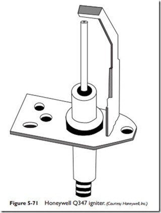
An igniter produces the spark for direct ignition of the main gas burner in various heating applications (gas furnaces, gas boilers, gas water heaters, etc.). The Honeywell Q347 igniter shown in Figure 5-71 consists of an internal electrode with a ceramic insula- tor, bracket, and ground strap.
Note
The flame-sensing rod is separate from the hot-surface igniter in most hot-surface ignition systems.
An igniter is used to provide the spark to ignite the main burner flame. Some igniters have an integral flame sensor. When this is the case, the igniter both ignites and senses (proves) the main gas burner flame.
The operating sequence of a system in which an igniter is used may be summarized as follows:
1. Room thermostat calls for heat.
2. Gas valve opens and gas flows to the burner(s).
3. Burner ignites when the gas reaches the main burner.
4. Spark igniter shuts off.
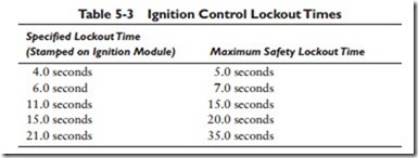
The duration of the spark operation must be within the igniter manufacturer’s specified lockout timing period. The igniter manufacturer will provide a chart of the ignition control lockout times in the service literature for the igniter. The example shown in Table 5-3 is for Honeywell’s Q347 igniter.
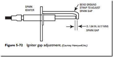
The electrode spark gap in the igniter must be within the speci- fied maximum (see Figure 5-72). If the gap is not within specifica- tions, it will have to be adjusted for optimum performance.
The flame rod of a combined igniterflame sensor unit must be immersed 1 inch in the burner flame to produce the best flame signal
(see Figure 5-73). Examples of poor flame conditions and their probable causes are illustrated in Figure 5-74.
The flame signal can also be adversely affected by a bent bracket, bent rod, or cracked ceramic insulator. Sometimes the bracket can be bent back into shape. If the rod is bent or the ceramic insulator is cracked, the igniter should be replaced.
Note
Always check the specifications of the replacement hot-surface igniter before installing it. Not all igniters have the same voltage or warm-up time as the original design.
The igniter used in a hot-surface ignition operating system differs in design from the type used in intermittent pilot or direct-spark ignition systems described in the preceding paragraphs (see Figure 5-75).
Be careful when replacing a hot-surface igniter because they are fragile and easily damaged. Sometimes a crack in the igniter surface is so small that it is not visible. A cracked hot-surface igniter may still work, but it will have a much shorter service life. After it is installed, check the hot-surface igniter for any inconsistencies in its glow pattern.
