Typical Control loops
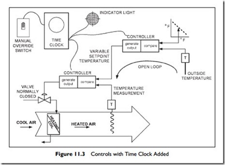
Having considered the basics of control loops in the previous section, now lets look at some real, more complete, control loops. We will start by adding time control, another open loop, to our previous example, as Figure 11.3.
A time clock now provides power to the controllers according to a schedule. Typical commercial thermostats include the 5–1–1 time clock function. 5–1–1 means that they have independent time schedules for the 5 weekdays, 1 for Saturday, and 1 for Sunday.
The system shown also has a manual-override switch that allows the occupant to switch the system ‘on’ when the time clock has it ‘off’. There is an obvious energy waste issue here, since the occupant may forget to switch back to the time clock. In most time clocks, the manual switch is part of the unit, rather than a remote switch as shown in the figure.
In addition, in the figure, there is an indicator light to show that the system is ‘on’. When the time clock switches ‘on’, it provides power to the lamp and power to the controllers. It has no idea whether the controllers are ‘on’ or even whether they are connected! The lamp does not indicate that the system is working. What it indicates is that power from the time clock is available. This type of open-loop indication is very common. If you are involved in trouble shooting equipment, think about the real information provided. Even if the lamp ‘off ‘, it does not mean there is no power to the controllers–the lamp could have burnt out!
In our diagram there is just one heating coil being controlled. In many pack- aged units, there will be two stages of cooling and two stages of heating. A single 5–1–1 thermostat will provide full control, turning ‘on’ one stage of cooling, and then the second stage, or one, and then the second stage of heating. The really good feature of a single, packaged thermostat is that there cannot be any overlap of control. For example, if a separate thermostat were used for heating and another for cooling, they could mistakenly be set so that the first stage of heating was ‘on’ when the first stage of cooling starts – a real waste of energy.
This issue of staging controls so that energy use is minimized is important in many areas. An example is the sequencing of control in a VAV box with a reheat coil. A VAV system provides cold air for cooling and ventilation. Should a zone require less cooling than is provided at the minimum airflow for ventilation, then the reheat coil is turned on. In the control system for the box, there are two important requirements:
1. The heating coil must only be activated at minimum airflow.
2. There must be minimal cycling between ‘coil on’ and ‘coil off’.
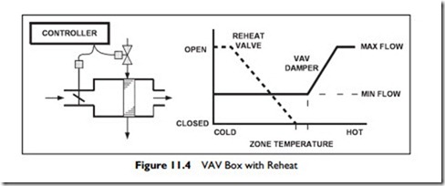
To achieve this, a single controller is used to control both the airflow and the coil, in sequence. The heating valve and volume damper are normally closed. The volume damper has a minimum setting for minimum ventilation.
As an example, the box and controller actions are shown in Figure 11.4. Starting on the left, when the space is cold, the controller opens the heating valve fully. As the zone warms up, the controller closes the heating valve.
Once the heating valve is closed, there is a dead band of temperature change (no heating, no additional cooling) before the controller starts to open the volume damper to increase the cooling up to maximum.
In addition to the simple control loops we have discussed, there are more complex loops that have many inputs. Staying with VAV for a moment, there are many systems where the fan speed is controlled by the requirements of the VAV boxes. A system, for example, might have 50 or more boxes. We want each to have enough air but we don’t want to run the fan any more than needed. To manage this, we need to know when each box has adequate air flowing through it.
A VAV box has enough air if its damper is not fully open. Thus, we would be very confident that if every box has its damper at less that 95% open, there is enough air pressure in the system. However, determining if every box meets this condition is only practical in a DDC system. We will begin to examine these DDC systems in the next section.

