DOWNFEED ONE-PIPE SYSTEM
The downf eed one-pip e sy stem (also referred to as the one pipe over sy stem or simply the downfe ed sy stem) is characterized by having the heat emitting units located below the supply mains. The condensation drips through the risers , thereby keeping the supply main relatively free of the condensation.
The downfeed one-pipe system is well suited for buildings two to five stories high because if the heat emitting units were fed from below , the risers would have to be excessively large. Instead of a steam main encircling the basement , it is carried to the attic, forming a central riser for all the heat emitting units. The branches in the attic correspond to the mains in the systems already de scribed, but do not carry any condensation from the heat emitting units. These branches connect with ·the drops or down flow pipes which feed the heat emitting units and drain the condensation.
As shown in Fig. 11, steam flows from the boiler up the central upfiow pipe through the branches and down through the drops or downflow pipes. The branches being inclined, any water or condensation in the steam drains into the upfiow riser. The steam passes to the heat emitting units through the connecting pipes. Condensation forming in the units drains through these connecting pipes into the downflow pipes. Air valves or vents are provided to rid the system of air. It should be noted 1that there is no reverse flow of condensation in the drop pipes. As a result, pipe sizes can be made smaller because, with parallel flow, steam velocities can be higher than in the one-pipe system.
ONE-PIPE CIRCUIT SYSTEM
In the one-pipe circuit system the steam main is carried entirely around the basement, taken off from the boiler by an elbow at the high point as in Fig. 12.
Note that the main must incline all the way from the high point to the low point. To allow for this inclination requires twice as much rise between high and low points as with the divided cir cuit system; that is, where there are two mains taken off from a T connection.
The one-pipe system is adapted for a rectangular building of low or moderate size. The size of the main (since all the steam flows through it) must be larger in size than the divided circuit system. However, especially in large installations, a saving in piping may be made by installing a “tapered main.” A tapered main is one which is reduced in size along its length by connecting lengths of different size pipes with reducers. Eccentric reducers should be used ·to avoid water pockets which would interfere with the proper drainage of the condensation. The risers are con nected by being tapped from the main at various points to serve the heat emitting units.
In a one-pipe system, the condensation drains into the main and flows in the same direction as the steam flow, being carried to the drip pipe, thence into the boiler. Since there is no return pipe as with the relief system, the circuit arrangement is less expensive to install.
Proportioning a tapered main is very important. The amount of condensation increases from the beginning to the end of the main and near the end is considerable, depending upon the num ber of heat emitting units. Due allowance should be made for 1his and too much tapering should be avoided.
ONE-PIPE DIVIDED CIRCUIT NONRELIEF SYSTEM
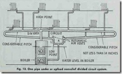
The one-pipe divided circuit nonrelief system differs from the one just described in that there are two mains at 1he high point taken off by a tee as in Fig. 13. These mains terminate in aU-shaped drip connection (LF) at the low point. Each should be vented with a quick vent as shown. Evidently each main takes care of only half the total condensation.
This steam heating system is suited to long buildings with a boiler located near the center. The end of each main is connected to a separate drip pipe connected with a common return, giving separate seals for each end.
For proper operation, these ends should not be at a lower elevation than 14 inches above the boiler water line. The individual seals make the two halves of the divided circuit independent, which is desirable for unequal loads. Thus, there may be consid erable difference between the pressure at (L) and (F), each being what is necessary to balance the load.
ONE-PIPE CIRCUIT SYSTEM WITH LOOP
The one-pipe circuit system with loop is adapted to L-shaped buildings, a circuit being used for the main building and a loop (tapped from the circuit) servicing ·the wing (Fig. 14). The mains are installed for the proper drainage of the condensation by pro viding two high points: one at the beginning of the circuit and the other at the beginning of the loop, ·thus giving ample margin above the boiler water line for liberal pitch in both the circuit and the loop. This is clearly shown in the illustration.
The low point of the loop is higher than the low point of tthe circuit, because the pressure at the end of the loop is less than the pressure at the end of the circuit. This requires a longer vertical drip pipe since the liquid column rises higher to balance ·the lower pressure.
![Fig.--11.-One--pipe--overhead--feed-[2] Fig.--11.-One--pipe--overhead--feed-[2]](http://machineryequipmentonline.com/hvac-machinery/wp-content/uploads/2020/04/Fig.-11.-One-pipe-overhead-feed-2_thumb.jpg)
![Fig.-12.-One-pipe-under-or-upfeed-no[2] Fig.-12.-One-pipe-under-or-upfeed-no[2]](http://machineryequipmentonline.com/hvac-machinery/wp-content/uploads/2020/04/Fig.-12.-One-pipe-under-or-upfeed-no2_thumb.jpg)

![F1g.--14.-One--pipe--under--or--upfe[1] F1g.--14.-One--pipe--under--or--upfe[1]](http://machineryequipmentonline.com/hvac-machinery/wp-content/uploads/2020/04/F1g.-14.-One-pipe-under-or-upfe1_thumb.jpg)