The Solar Tower
We mentioned solar power conversion as an application for Stirling engines. Here, we discuss an interesting application for solar power conversion, which relies on the chimney effect, which, in turn, relies on the variation of air pressure with height as expressed in the barometric formula (2.25).
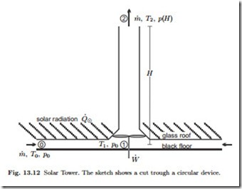
The solar tower, or solar chimney, sketched in Fig. 13.12, works as follows: Solar radiation provides heat Q˙ 8 which passes through a glass roof, is absorbed by black mats on the ground, and the warm mats heat up air. The
warm air rises through the chimney and drives turbines which are connected to a generator to produce the power W˙ . When a layer of water is placed below the black mats (e.g., one might use black sacks filled with water), the heat provided from the sun goes partly into air and partly into the water. When the solar heat supply stops after sunset, the warm water heats the air, and the tower still produces electricity until the water has cooled down. An experimental plant with a 180 m tower was build some years ago in Spain, plans to build a tower with a height of 1000 m and a diameter of the glass roof of 6 km in Australia are presently on hold.
We aim at a thermodynamic evaluation of the solar tower, and ask in particular for its thermal efficiency. The temperatures involved are rather low, and thus we can use the cold air approximation, i.e., we assume the specific heats of air to be constants. The exterior air is assumed to have constant temperature T0, and the pressure depends on height z according to the barometric formula, p (z) = p0 exp r− gz l with p0 the pressure at the ground.
The incoming air is at {T0, p0}, and as it flows towards the turbines it is heated isobarically until it reaches the temperature T1 just before the turbines. To compute this temperature, we apply the first law for open systems between the outer rim and the point just before the turbine. Since the radius is large, the flow velocity V0 at the outer rim can be neglected, and the first law gives
The velocity at turbine inlet is related to mass flow by V1 is the cross section of the chimney at point 1, and the pressure of the flow remains constant, so that ρ1 = ρ0 T0 . Thus we find
To avoid a detailed discussion of heat transfer mechanisms, we assume the temperature T1 to be given, so that the above is an equation for the heat supply from the sun, Q˙ 8. Note that due to emission and absorption of radiation the temperature T1 is limited, as in a greenhouse. A proper radiation heat transfer analysis must be performed to establish the size the glass roof must have, so that the specified temperature T1 is reached.
Next, we consider the flow between the turbine inlet (Point 1) and the exhaust from the chimney (Point 2). We assume that turbine and chimney are adiabatic, and, for simplicity, that the flow is reversible, so that it is isentropic. The first law gives
This equations gives power W˙ in dependence of mass flow m˙ , all other quantities are given by material and construction.
Before we study the full result, we have a look at a further simplification, where the contribution of kinetic energies, that is all terms with factor m˙ 2, are ignored. In this case (13.24) and (13.23) reduce to
which yields a thermal efficiency of
Accordingly, it is beneficial to build the tower as high as possible. For a height of 200 m the efficiency is η = 0.65% and this increases to η = 3.25% when the height is raised to 1000 m. Note that the thermal efficiency is very low nevertheless. Here it must be considered that the main investment is to build the plant, while the energy source—solar radiation—is available for free, as long as no clouds are present, which is, of course, why one would build such a solar tower power plant in a sunny country.
Since the investment costs are high, one will aim to harvest as much power as possible, which will be achieved by optimizing the operating conditions. We return to (13.24) and determine the optimum mass flow to maximize power from the condition dW˙ /dm˙ = 0 as


