Dual Cycle
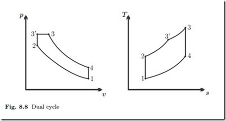
In real engines the combustion process is neither just an instantaneous, i.e., isochoric, explosion as assumed above for the Otto cycle, nor is it a slow isobaric combustion as assumed above for the Diesel cycle. To have a somewhat better model, one can modify the description of the fuel combustion process as a combination of isochoric and isobaric heating. The resulting cycle is the dual cycle:
Figure 8.8 shows the corresponding diagrams. Depending on the choice of parameters, one can model Otto and Diesel engines as a dual cycle. The dual step would have a more pronounced isochoric and smaller isobaric step for Otto engines, and a smaller isochoric but more pronounced isobaric step for Diesel engines. Moreover, Otto engines have compression ratios below 12, while Diesel engines have higher compression ratios.
Atkinson Cycle
At the end of the expansion process in the Otto and Diesel cycles, the working fluid is at elevated pressure and temperature, and more work could be extracted. One method to use this work is to drive a turbo charger, which essentially is a compressor that is used to fill the cylinders with air-fuel mix (Otto) or air (Diesel) at elevated pressures. With this, the mass of air in the engine is higher than when it only draws air at environmental pressure p0.
Since the power output of the engine is proportional to mass, W˙ = n˙ mw , 2 8 turbo charging increases the power output, or gives the same power from a smaller engine.
An alternative method to make use of the work potential is used in Atkinson engines. The Atkinson cycle is a modification of the Otto cycle where the compression and expansion strokes have different lengths. Specifically, the expansion stroke is longer than the compression stroke, so that—in the best case—the pressure at the end of expansion is equal to the intake pressure.
The early engines build by James Atkinson (1846–1914) relied on mechanical valve control. Since valves can be controlled electronically, Atkinson’s ideas become more prominent, and engines based on the Atkinson cycle are routinely used in modern hybrid cars.
To achieve the Atkinson cycle in an actual engine one uses clever control of the valves. In the Otto engine the valves close at the end of the intake stroke (Stroke I), and as the piston reverses its direction, compression starts immediately (Stroke II). In an Atkinson engine the valve remains open during the beginning of the second stroke, so that some of the intake is pushed back into the intake manifold. The valve closes a bit later (at volume V1) and compression commences. Thus, compression occurs only on part of Stroke II. The valves remain closed for the full expansion (Stroke III), so that the expansion stroke is longer than the compression stroke. At the end of expansion, the valves open and the exhaust stroke (Stroke IV) begins. Computerized control
of the valve timing allows to vary the length of the compression stroke to optimize engine performance for the current driving conditions.
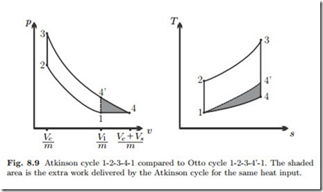
The processes in the ideal air-standard Atkinson cycle are:
1-2 adiabatic compression
2-3 isochoric heating (air-fuel mix explodes)
3-4 adiabatic expansion
4-1 isobaric cooling (exchange of working fluid)
The corresponding process diagrams are depicted in Fig. 8.9. The figure also indicates the point 41 at which the expansion would finish in the Otto cycle. The shaded areas in the two diagrams indicate the additional work generated in the Atkinson cycle as compared to the Otto cycle. The compression ratio
Therefore, the thermal efficiency of the Atkinson cycle is larger than that of the Otto cycle with the same compression ratio.
In order to have the ideal Atkinson cycle performed, the heat addition q23 must be such that T3 = T1 re . If more heat is added, so that the temperature T3 lies above this value, the pressure p4 at the end of expansion will be above the inlet pressure p1. In this case, the cooling process (which models exhaust
and intake) would include an isochoric process:
1-2 adiabatic compression
2-3 isochoric heating
3-4’ adiabatic expansion
4’-4 isochoric cooling
4-1 isobaric cooling
The corresponding process diagrams are shown in Fig. 8.10. Work and heat for the processes are
1-2 isentropic: w12 = u1 − u2 < 0 , q12 = 0
2-3 isochoric: w23 = 0 , q23 = u3 − u2 > 0
3-4’ isentropic: w341 = u3 − u41 > 0 , q341 = 0
4’-4 isochoric w41 4 = 0 q41 4 = u4 − u41 < 0
4-1 isobaric: w41 = p1 (v1 − v4) < 0 , q41 = h1 − h4 < 0
The thermal efficiency of the overheated Atkinson cycle is below that of the ideal Atkinson cycle. In the cold-air approximation one finds


