Styles of turbine
Often, if the stage loading and flow coefficient are fixed by the overall requirements of the turbine and the principal design constraints, only one parameter remains that the designer has the freedom to change in the preliminary design. The classification of different styles of turbine design is most conveniently described by the reaction, because this relates to the turbine blade geometries. There are two extremes: zero reaction, where the rotor and stator shapes are very different, and 50% reac- tion, where the rotor and stator shapes are symmetric. The advantages and disadvantages of both these styles are discussed below.
Zero reaction stage
Walker and Hesketh (1999) summarize the advantages of low reaction as enabling a high stage loading with low interstage swirl, low thrust on the rotor, robust rotor blades, and lower tip leakage flows (due to a low-pressure drop across the rotor). However, they also point out that low reaction can lead to boundary layer separation from the highly cambered rotor blades and they show how the increased stage loading almost invariably leads to lower efficiency. Low reaction designs are regularly applied in steam turbines, where their advantages are most beneficial and they enable a reduction in the total number of stages required, but they are not currently used in gas turbines.
From the definition of reaction, when R 5 0, Eq. (4.3) indicates that h2 5 h3 and, thus, all the enthalpy drop occurs across the stator. From Eq. (4.13b), we can show that
Since the axial velocity is constant, this means that the relative speed of the flow across the rotor does not change. The Mollier diagram and velocity triangles corresponding to these conditions are sketched in Figure 4.6. From this it is also clear that, since h02rel 5 h03rel and h2 5 h3 for R 5 0, it follows that w2 5 w3. It will be observed in Figure 4.6 that, because of irreversibility, there is a pressure drop through the rotor row. The zero reaction stage is not the same thing as an impulse stage; in the latter case there is, by definition, no pressure drop through the rotor. The Mollier diagram for an impulse stage is shown in Figure 4.7, where it is seen that the enthalpy increases through the rotor. As shown by Eq. (4.3a) this means that the reaction is negative for the impulse turbine stage when account is taken of the irreversibility.
50% Reaction stage
Havakechian and Greim (1999) summarize the advantages of 50% reaction designs as symmetrical velocity triangles leading to similar blade shapes and reduced cost, low turning and highly
accelerating passages leading to lower losses, an expansion split into two steps leading to subsonic Mach numbers, and improved performance over a range of operating conditions. However, they concede that 50% reaction designs lead to increased turbine part count relative to low reaction designs since, for low interstage swirl, roughly twice as many stages are needed. Also, the greater expansion through the rotors increases the thrust on the rotor bearings and increases leakage losses. 50% reaction designs are very common in gas turbines, where the requirement for maximum efficiency is paramount. In gas turbines higher stage loadings are achieved by increasing the interstage swirl angle, α1. In steam turbines, both 50% reaction and low reaction designs are regularly applied and the two approaches remain competitive.
The symmetrical velocity diagram for the 50% reaction case is shown in Figure 4.8. With R 5 0.5, from Eq. (4.13a) combined with Eq. (4.15), it is found that
Similarly, it can be shown that β3 5 α2 as well, proving that the velocity triangles are indeed symmetric. Figure 4.8 has been drawn with the same values of cx, U, and ΔW as in Figure 4.6 (the zero reaction case) to emphasize the difference in flow geometry between the 50% reaction and zero reaction stages.
EXAMPLE 4.2
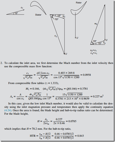
A low-pressure turbine within a turbofan jet engine consists of five repeating stages. The turbine inlet stagnation temperature is 1200 K and the inlet stagnation pressure is 213 kPa. It operates with a mass flow of 15 kg/s and generates 6.64 MW of mechanical power. The stator in each turbine stage turns the flow from 15o at stator inlet to 70o at stator outlet. The turbine mean radius is 0.46 m and the rotational shaft speed is 5600 rpm.
1. Calculate the turbine stage loading coefficient and flow coefficient. Hence, show that the reaction is 0.5 and sketch the velocity triangles for one complete stage.
2. Calculate the annulus area at inlet to the turbine. Use this to estimate the blade height and the hub-to-tip radius ratio for the stator in the first turbine stage. Take γ 5 1.333, R 5 287.2 J/kg K, and Cp 5 1150 J/kg K.
Solution
1. The mean blade speed can be calculated from the mean radius and angular speed:


