Hot-Water heating systems use water as the medium for con veying and transmitting the heat to the various rooms and spaces within a structure. The motive force for the water in these systems is based either on the gravity flow principle or forced circulation. The latter type (referred to as hydronic or forced hot-water heat ing) is the most commonly used method.
CLASSIFYING HOT-WATER HEATING SYSTEMS
Hot-water heating systems can be classified in a number of different ways depending on the criteria used. Three broad classi fication categories based on the following criteria are generally recognized:
1. Type of water circulation,
2. Piping arrangement,
3. Supply water temperature.
In all hot-water heating systems, the water is circulated either by forcing it through the line or by allowing H to flow naturally. The latter is referred to as a gravity hot-water heating system. because circulation resul,ts from the difference in weight (specific gravity) of the water due to temperature differences (heavy when cold; light when hot). In a forced hot-water heating system, the accelerated circulation of the water can result from several commonly employed methods, including:
( 1) using high pressures;
(2) super heating the circulating water and condensing the steam;
(3) introducing steam or air into the main riser pipe; (4) using a combination of pumps and local boosters; and (5) using pumps alone.
The four principal piping arrangements used in hot-water systems are as follows:
1. One-pipe system,
2 Two-pipe direct return system,
3. Two-pipe reverse return system,
4. Series-loop system.
These piping arrangements are described and illustrated in several sections of this chapter (see, for example, ONE-PIPE SYSTEM, TWO-PIPE DIRECT RETURN SYSTEM, etc.).
If a hot-water heating system uses supply water temperatures above 250 °F., it is classified as a high temperature system. High temperature systems are used in large heating installations such as commercial or industrial buildings. A low temperature system is one having a supply water temperature below 250°F and is used in residences and small buildings.
ONE-PIPE SYSTEM
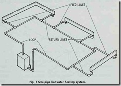
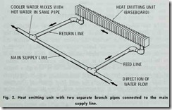
A one-pipe system (Fig. 1) is one in which a single main pipe is used to carry the hot water throughout the system. In other words, the same pipe that carries the hot water to the heat emit ting units (i.e. the radiators, convectors, etc.) in the various rooms and spaces within the structure also returns the cooler water to the boiler for reheating. Each heat emitting unit is connected to the supply main by two separate branch pipes (a separate feed and return line) (Fig. 2).
The hot water flows from the boiler or heat exchanger (if a team boiler is the heat source) to ·the first heat emitting unit. through it to the second unit, and so on through each of ·the heat emitting units in the one-pipe system until it exits the last one and returns to the boiler or heat exchanger.
One-pipe systems may be operated on either forced or gravity circulation. Special care must be taken to design the system for the temperature drop found in the heat emitting units farthest from the boiler. This is particularly true of one-pipe systems designed for gravity circulation.
A principal advantage of a one-pipe system is that one or more heat emitting units can be shut off without interfering with the flow of water to other units. This is not true of series-loop systems in which the units are connected in series and form a part of the supply line.
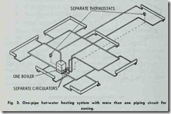
In some large one-pipe systems, zoning is possible by pro viding for more than one piping circuit from the boiler (Fig. 3). In such cases, each piping circuit is equipped with its own thermo stat and circulating pump. Sometimes ·these circuits are erron eously referred to as “loops” which results in confusing them with the piping arrangement in a series-loop system.
SERIES-LOOP SYSTEM
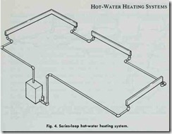
In the series-loop system (Fig. 4), the heat emitting unhs form a part of the piping circuit (i.e. loop) which carries the hot water from the boiler around the rooms and spaces within the structure, and back to the boiler again for reheating. In other words, there are no branch pipes connecting the main supply pipe to the heat emitting units as in the one-pipe system. In the series loop system, the hot water flows from ·the boiler through a length of the main supply pipe to the first heat emitting unit in the circuit (loop). It then flows through ·the unit to a leng.th of the main supply pipe connected at the opposite end; flows through this pipe to the second heat emitting unit in the circuit, and so until the en tire circuit is completed.
The series loop system is cheaper and easier to install than other piping arrangements, because it eliminates the need for branch pipes and reduces the amount of pipe used in the main circuit to the comparatively short lengths connecting the heat emit ting units. There is no need for one continuous length of main pipe.
Because the heat emitting units are connected in series and constitute a part of the main supply line, the same hot water sup ply passes through each unH in succession. As a result, the heat emitting unit closest to the boiler receives the hottest water, whereas those farther away receive water several degrees cooler. Furthermore, individual units cannot be shut off (unless there is a special bypass piping arrangement) without obstructing the flow of water to units further along the line.
TWO-PIPE DIRECT-RETURN SYSTEM
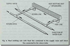
In a two-pipe direct-return system (Fig. 5) hot water returns directly to the boiler from each heat emitting unit. In other words, the hot water supply and return mains are separate pipes. The heat emitting units are connected to the supply and return lines by separate branches (Fig. 6).
Each heat emitting unit represents the mid-point in a complete circuit within a two-pipe direct-return system. The boiler com pletes ·the circuit. The farther a heat emitting unit is located from the boiler, the greater the length of the piping in the circuit. Although this factor causes problems in balancing the water sup ply among the various circuits, balancing can be achieved in a number of ways, including: ( 1) balancing cocks, (2) proper pipe sizing, or (3) using a reverse-return system.
TWO-PIPE REVERSED-RETURN SYSTEM
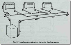
A two-pipe reversed-return syst em (Fig. 7) achieves a balance in the water supply by creating circuits to the radiators of approxi mately equal length. Instead of allowing the return supply of water •to proceed directly to the boiler from each radiator , the return main carries the water in the opposite direction for a predeter mined distance before turning back :to the boiler. The first radiator has the shortest supply main, but the longes·t return main. For the farthest radiator, the reverse is true. Regardless of the position of a radiator in the system, the total length of pipe within the circuit of w ich it forms a part Will be essentially the same as that of any other circuit.
COMBINATION PIPE SYSTEMS
Sometimes two or three different types of pipe arrangements will be combined in a single heating system. For example, it is not unusual .to find a two-pipe reversed-return system combined with a series-loop system. Combination pipe systems are usually found in commercial or industrial buildings, and are fitted to speci fic design needs.
ZONING A TWO-PIPE SYSTEM
Balancing problems for two-pipe hydronic heating systems in larger houses and buildings can be solved by spliHing the existing system into two or more separate zones independently controlled by their own thermostats. This can be accomplished by installing a two-position valve in the hot water supply line. The valve is actuated by its own thermostat (Fig. 8).
RADIANT PANEL HEATING
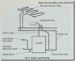
Forced hot water can also be used in a radiant panel heating system (Fig. 9). In this type of heating system, no radiators or convectors are used. The hot water circulates through pipes con cealed in the floor, ceiling, or walls, which function as heat emit ting surfaces. Radiant baseboard systems are also used. The principles of radiant heating are described in greater detail in Chapter 11, Volume 2 (RADIANT HEATING).
