High Mach number compressor stages
As introduced in Chapter 3, the performance of compressor blades deteriorate once the relative inlet Mach number exceeds about 0.7, because the relative Mach numbers within the blade passages
exceeds unity and extra losses are generated by shock waves and thicker boundary layers. Furthermore, high Mach numbers reduce the operating range of a compressor because the flow becomes more sensitive to changes in inlet angle.
However, there are two key advantages of high Mach number compressor stages. Firstly, high relative Mach numbers in a compressor imply a high mass flow per unit area, which leads to a more compact (lower diameter) machine for a given mass flow. Secondly, high Mach numbers are caused by high blade speeds, which enable greater work input to the flow and, hence, higher pressure ratios. Using the definitions of stage loading and polytropic efficiency, the stage pressure ratio for a compressor can be written as
This shows that high stage pressure ratios can be achieved by high blade speeds combined with high stage loading and efficiency. In modern transonic compressors, rotor inlet relative Mach num- bers of up to 1.7 are now used and single-stage pressure ratios greater than 2 are possible.
Calvert and Ginder (1999) detail the design of transonic compressor stages. They also describe the evolution of modern transonic compressors and the major advances that have been made. Transonic compressor stages are currently used within the single-stage fans of high bypass ratio jet engines, in multistage fans within low bypass ratio engines and in the front stages of multistage compressors. The fan of a civil jet engine is a particularly important component as it produces over 80% of the thrust of a modern civil aircraft engine. High mass flow per unit area is needed to mini- mize the engine size, and inlet relative Mach numbers are around 1.4 at the tip. Polytropic efficiencies above 90% are typical and current design pressure ratios are between 1.6 and 1.8.
To alleviate the effects of high relative Mach numbers in transonic compressors, very thin blades are used to reduce their blockage and typically the thickness-to-chord ratio of the blades is only a few percent. In addition, to reduce the peak Mach number on the blade surface, the blades have very low camber, with only a few degrees of turning. As a result, the blade sections toward the tip of a high-speed compressor resemble sharp, thin, and almost flat plates.
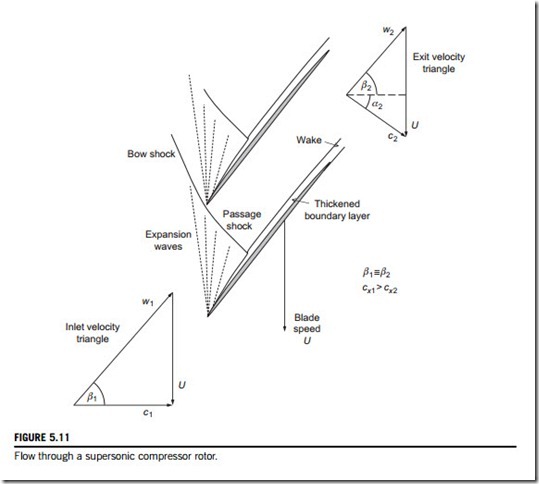
Figure 5.11 shows the flow pattern within a high-speed compressor rotor blade with a supersonic inlet relative Mach number. As the operating point of the compressor changes, the position of the passage shock varies. When the flow is fully choked, the shock moves rearward so that it is fully swallowed within the blade passage. At lower mass flow rates, when the compressor is closer to stall, the shock structure is expelled from the front of the blade passage. The operating point corresponding to peak efficiency usually occurs when the shock wave is close to the blade leading edge.
It is interesting to understand how the shock pattern in Figure 5.11 leads to a very high work input into the flow passing through the compressor. Consider the velocity triangles at inlet and exit from the compressor rotor. Across the passage shock wave, as drawn in Figure 5.11, the flow does not turn significantly, but the density rises sharply. Hence, the relative velocity downstream of the shock will be much lower than upstream. Assuming the blade speed and relative flow angles are the same at rotor inlet and exit, the velocity triangles show that the turning of the flow in the absolute frame is purely a result of the flow slowing down in the relative frame. In contrast, a low- speed compressor rotor achieves a work input to the flow by turning the flow in both the relative and the absolute frames of reference.
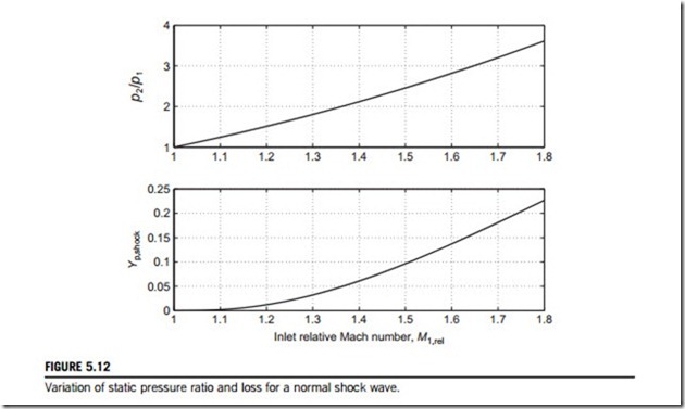
A normal shock wave in a supersonic compressor rotor leads to a rise in entropy in the flow, as given by Eq. (4.21), which can be expressed as a loss coefficient using Eq. (5.8) as
which can be expressed as a function of the inlet relative Mach number, M1,rel and γ. This function is plotted in Figure 5.12 for air as well as the corresponding variation of shock static pressure ratio, given by
This shows that the pressure rise delivered by a normal shock wave is high, whereas the shock loss itself is surprisingly low up to inlet relative Mach numbers of 1.5. However, it should be noted that the shock wave also generates loss indirectly through interaction with the blade boundary layers, which are thickened by the shock static pressure rise, and in some cases the flow can separate. Provided this risk of separation is avoided, a shock wave is a highly efficient way to compress flow, as demonstrated by the high efficiencies of modern transonic compressors.


