Main classes of transformer
Transformers are used for a wide variety of purposes, with the complete range of volt- age and power ratings as well as many special features for particular applications. The following covers the main types.
Transformers for electronics
Transformers for electronic circuits or for low-voltage power supplies are used to match the supply voltage to the operating voltage of components or accessories, or to match the impedance of a load to a supply in order to maximize power throughput. They may be used to match impedances in primary and secondary circuits using eqn 6.6.
The core is usually constructed in low-power transformers from C- and I-laminations or from E- and I-laminations. The windings are usually of round enamelled wire, and the assembly may be varnished or encapsulated in resin for mechanical consolidation and to prevent ingress of moisture. Increasing numbers of this type operate at high frequencies in the kilohertz range and use laminations of special steel often containing cobalt to reduce the iron losses.
Small transformers
These are used for stationary, portable or hand-held power supply units, as isolating transformers and for special applications, such as burner ignition, shavers, shower heaters, bells and toys. They may be used to supply three-phase power up to 40 kVA at frequencies up to 1 MHz. These transformers are usually air insulated, the smaller units using enamelled windings wires and ring cores and the larger units using C- and I- or E- and I-laminated cores.
Safety is a major concern for these transformers and they are identified as class I, class II or class III. Class I units are insulated and protected by an earth terminal. Class II transformers have double insulation or reinforced insulation. Class III transformers have outputs at Safety Extra-Low Voltages (SELV) below 50 V ac or 120 V dc (see section 16.2.2.4 for background on SELV).
Distribution transformers
These are used to distribute power to domestic or industrial premises. They may be single-phase or three-phase, pole-mounted or ground-mounted, and they have ratings ranging from 16 kVA up to 2500 kVA.
The windings and core are immersed in mineral oil, with natural cooling, and there are two windings per phase. The primary (high-voltage) winding has a highest voltage ranging from 3.6 kV to 36 kV; the secondary (low-voltage) winding voltage does not exceed 1.1 kV. The high-voltage winding is usually provided with off-circuit tappings of ± 2.5 per cent, or +2 × 2.5 per cent, – 3 × 2.5 per cent.
The preferred values of rated output are 16, 25, 50, 100, 160, 250, 400, 630, 1000, 1600 and 2500 kVA, and the preferred values of short-circuit impedance are 4 or 6 per cent.
Losses are assigned from lists, for instance from BS 7281-1, or by using a loss– capitalization formula.
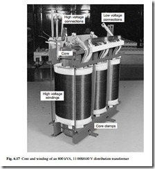
The core and windings of a typical distribution transformer rated at 800 kVA, 11 000/440 are shown in Fig. 6.17.
Supply transformers
These are used to supply larger industrial premises or distribution substations. Ratings range from 4 MVA to 30 MVA, with primary windings rated up to 66 kV and secondary windings up to 36 kV.
Transformers in this class are fluid cooled. Most supply transformers use mineral oil; but for applications in residential buildings, oil rigs and some factories, the coolant may be synthetic esters, silicone fluid or some other fluid with a higher fire point than mineral oil.
Transmission (or intertie) transformers
These are among the largest and highest voltage transformers in use. They are used to transmit power between high-voltage networks. Ratings range from 60 MVA to
1000 MVA and the windings are rated for the networks which they link, such as 33, 66, 132, 275 and 400 kV in the UK, or voltages up to 500 kV or 800 kV in other countries. The impedance of a transmission transformer is usually 18 per cent in the UK, or 8 per cent in continental Europe, but for some system conditions, an impedance of up to 30 per cent is used.
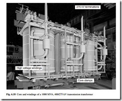
Transmission transformers are oil filled, and are usually fitted with oil pumps and radiator fans to assist cooling of the windings and cores. They are usually fitted with OLTCs, but some networks at 400 kV and 275 kV are linked by transformers without regulating windings. The core and windings of a three-legged transmission trans- former rated at 1000 MVA and 400 kV/275 kV/11 kV are shown in Fig. 6.18.
Generator (or step-up) transformers
Power is usually generated in large power stations at typically 18–20 kV, and generator transformers are used to step up this voltage to the system voltage level. These trans- formers are usually rated at 400, 500, 630, 800 or 1000 MVA.
Generator transformers are usually fitted with regulating windings and OLTCs.
Phase-shifting transformers
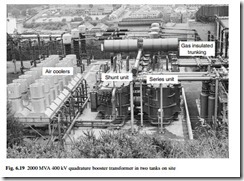
Where power is transmitted along two or more parallel transmission lines, the power flow divides between the lines in inverse proportion to the line impedances. Higher power is therefore transmitted through the line with lowest impedance and this can result in overload on that line, when the parallel line is only partly loaded. Phase-shifting
transformers are used to link two parallel lines and to control power flow by injecting a voltage 90° out of phase (in quadrature) with the system voltage into one line, at either leading or lagging power factor. Where the transformer controls the phase angle but not the voltage, the unit is known as a quadrature booster. Where the voltage is also controlled, the unit is known as a phase-shifting transformer. Figure 6.19 shows a 2000 MVA, 400 kV quadrature booster transformer on site; the unit is split between two tanks in order to meet construction limitations of size and weight.
Converter transformers
Where power is transmitted through an HVDC system, a converter station is used to change ac power to dc using multiple rectifier bridges. Direct current power is converted back to ac using inverter bridges. Converter transformers handle ac power and power at mixed ac/dc voltages by combining the power flow through 12 phases of rectifier/inverter bridges through dc valve windings.
The insulation structure must withstand all normal and abnormal conditions when ac voltage is mixed with dc voltage of differing polarities over the operating temperature range. The presence of dc currents may also cause dc saturation of the core, leading to abnormal magnetizing currents and variations in sound.
A phase of a three-phase converter transformer bank typically comprises a high-voltage primary winding and two secondary ac/dc valve windings. Three such transformers together form the two secondary three-phase systems; one is connected in delta and the other in star. Each secondary system feeds a six-pulse bridge and the two bridges are connected in series to form a 12-pulse arrangement, as shown schematically in Fig. 6.20. Two such transformer banks are used with the secondary circuits connected in opposite polarity to form a ±215 kV dc transmission system.
Railway transformers
Transformers for railway applications may be trackside units to supply power to the track, or on-board transformers in the locomotive or under the coaches, to power the drive motors.
Trackside transformers are subjected to uneven loading depending upon the position of the train in the railway system. On-board transformers are designed for the lowest possible weight, resulting in a high-loss performance. Modern train control systems using thyristors, GTOs or IGBTs subject the transformers to severe harmonic currents that require special design consideration.
Rectifier and furnace transformers
Special consideration is needed for transformers in industrial applications involving arc furnaces or heavy-current dc loads in electrochemical plant. The primary windings in such cases are usually rated at 33 kV or 132 kV in the UK, but the secondary wind- ings carry many thousands of amperes and are rated at less than 1 kV. Current sharing between parallel paths in the transformer becomes important because of the magnetic fields created by the high currents. These strong magnetic fields can cause excess heat- ing in magnetic steels if these are used in the structure of the transformer, because of the flow of proximity currents in the steel. To reduce this excess heating, non-magnetic steel is often used to form part of the tank or the cover.
The OLTCs in furnace transformers are subject to a heavy duty; they may perform hundreds of thousands of operating cycles a year, which is more than a lifetime’s duty for many transmission transformers.
Dry-type transformers
A dry-type construction is possible where a higher-temperature class of insulation is required than is offered by cellulose and a class ‘O’ or class ‘K’ fluid. Dry-type trans- formers use non-cellulosic solid insulation and the windings may be varnish dipped to provide a class ‘C’ capability, or vacuum encapsulated in epoxy resin to form a class ‘F’ or class ‘H’ system. (See Table 3.4 for details of the temperature classification of insulation.) Ratings are generally up to 30 MVA at voltages up to 36 kV, but cast resin transformers have recently been successfully manufactured at 110 kV using a novel winding design. Overload performance is limited but it can be augmented by the use of cooling fans.
This type is more expensive than a fluid-filled equivalent, and because of the reduced fire risk they are used in special applications where the public are involved, such as underground tunnels, residential blocks of flats or oil-rigs.
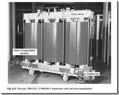
A typical cast-resin transformer rated 2500 kVA, 11 000/440 V is shown in Fig. 6.21.
Gas-filled transformers
For applications where low flammability is paramount, designs have been developed in which the transformer is insulated and cooled with SF6 gas. This provides an alternative to dry-type construction where the risk of fire must be eliminated and the possible contamination of the environment by oil spillage must be avoided. High-voltage SF6 transformers are available at ratings up to 300 MVA at 275 kV and prototype designs have been tested at up to 500 kV. Gas-filled transformers and reactors are more expensive than oil-filled units but the costs may be justified to eliminate a risk of fire,
particularly at a site where the cost of land is high and where the overall ‘footprint’ of the unit can be reduced by the elimination of fire-fighting equipment.


