Loadings
Distribution transformers are output rated; they can deliver their rated kVA without exceeding temperature rise limits when the following conditions apply:
• The secondary voltage and the voltage/frequency do not exceed 105% of rating. So, a transformer is a constant kVA device for a voltage from 100 to 105% (the standards are unclear below that, so treat them as constant current devices).
• The load power factor ≥ 80%.
• Frequency ≥ 95% of rating.
The transformer loading and sizing guidelines of many utilities are based on ANSI/IEEE C57.91-1981.
Modern distribution transformers are 65°C rise units, meaning they have normal life expectancy when operated with an average winding temperature rise above ambient of not more than 65°C and a hottest spot winding tem- perature rise of not more than 80°C. Some older units are 55°C rise units, which have less overloading capability.
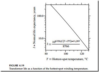
At an ambient temperature of 30°C, the 80°C hottest-spot rise for 65°C rise units gives a hottest-spot winding temperature of 110°C. The hot-spot tem-
perature on the winding is critical; that’s where insulation degrades. The insulation’s life exponentially relates to hot-spot winding temperature as shown in Figure 4.19. At 110°C, the normal life expectancy is 20 years. Because of daily and seasonal load cycles, most of the time temperatures are nowhere near these values. Most of the time, temperatures are low enough not to do any significant insulation degradation. We can even run at tem- peratures above 110°C for short periods. For the most economic operation of distribution transformers, they are normally sized to operate at significant overloads for short periods of the year.
We can load distribution transformers much more heavily when it is cold. Locations with winter-peaking loads can have smaller transformers for a given loading level. The transformer’s kVA rating is based on an ambient temperature of 30°C. For other temperatures, ANSI/IEEE C57.91-1981 suggests the following adjustments to loading capability:
• > 30°C: decrease loading capability by 1.5% of rated kVA for each °C above 30°C.
• < 30°C: increase loading capability by 1% of rated kVA for each °C above 30°C.
Ambient temperature estimates for a given region can be found using historical weather data. For loads with normal life expectancy, ANSI/IEEE C57.91-1981 recommends the following estimate of ambient temperature:
• Average daily temperature for the month involved — As an approximation, the average can be approximated as the average of the daily highs and the daily lows.
For short-time loads where we are designing for a moderate sacrifice of life, use:
• Maximum daily temperature
In either case, the values should be averaged over several years for the month involved. C57.91-1981 also suggests adding 5°C to be conservative. These values are for outdoor overhead or padmounted units. Transformers installed in vaults or other cases with limited air flow may require some adjustments.
Transformers should also be derated for altitudes above 3300 ft (1000 m). At higher altitudes, the decreased air density reduces the heat conducted away from the transformer. ANSI/IEEE C57.91-1981 recommends derating by 0.4% for each 330 ft (100 m) that the altitude is above 3300 ft (1000 m).
Load cycles play an important role in determining loading. ANSI/IEEE C57.91-1981 derives an equivalent load cycle with two levels: the peak load and the initial load. The equivalent two-step load cycle may be derived from a more detailed load cycle. The guide finds a continuous load and a short- duration peak load. Both are found using the equivalent load value from a more complicated load cycle:
The continuous load is the equivalent load found using the equation above for 12 h preceding and 12 h following the peak and choosing the higher of these two values. The guide suggests using 1-h time blocks. The peak is the equivalent load from the equation above where the irregular peak exists.
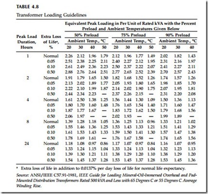
The C57.91 guide has loading guidelines based on the peak duration and continuous load prior to the peak. Table 4.8 shows that significant overloads are allowed depending on the preload and the duration of the peak.
Because a region’s temperature and loading patterns vary significantly, there is no universal transformer application guideline. Coming up with standardized tables for initial loading is based on a prediction of peak load, which for residential service normally factors in the number of houses, aver- age size (square footage), central air conditioner size, and whether electric heat is used. Once the peak load is estimated, it is common to pick a trans- former with a kVA rating equal to or greater than the peak load kVA estimate. With this arrangement, some transformers may operate significantly above their ratings for short periods of the year. Load growth can push the peak
load above the peak kVA estimate, and inaccuracy of the load prediction will mean that some units are going to be loaded more than expected. The load factor (the ratio of average demand to peak demand) for most distribution transformers is 40 to 60%. Most distribution transformers are relatively lightly loaded most of the time, but some have peak loads well above their rating. In analysis of data from three utilities, the Oak Ridge National Laboratory found that distribution transformers have an average load of 15 to 40% of their rating, with 30% being most typical (ORNL-6925, 1997).
The heat input into the transformer is from no-load losses and from load losses. The economics of transformer application and purchasing involve consideration of the thermal limitations as well as the operating costs of the losses. Transformer stocking considerations also play a role. For residential customers, a utility may limit inventory to 15, 25, and 50-kVA units (5, 10, 15, 25, 37.5, 50-kVA units are standard sizes).
Some utilities use transformer load management programs to more precisely load transformers to get the most economic use of each transformer’s
life. These programs take billing data for the loads from each transformer to estimate that transformer’s loading. These programs allow the utility to more aggressively load transformers because those needing changeout can be targeted more precisely. Load management programs require data setup and maintenance. Most important, each meter must be tied to a given transformer (many utilities have this information infrastructure, but some do not).
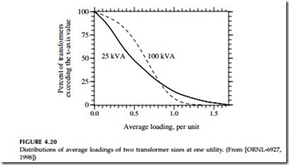
Transformer loadings vary considerably. Figure 4.20 shows the distribu- tion of average loadings on two sizes of transformers at one typical utility. Most transformers are not heavily loaded: in this case, 85% of units have average loadings less than the nameplate. Many units are very lightly loaded, and 10% are quite heavily loaded. Smaller units have more spread in their loading.
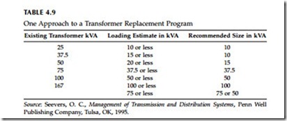
Seevers (1995) demonstrates a simple approach to determining trans- former loading. Their customers (in the southern U.S.) had 1 kW of demand for every 400 kWh’s, regardless of whether the loads peaked in the winter or summer. Seevers derived the ratio by comparing substation demand with kWh totals for all customers fed from the substation (after removing pri- mary-metered customers and other large loads). To estimate the load on a given transformer, sum the kWh for the month of highest usage for all customers connected to the transformer and convert to peak demand, in this case by dividing by 400 kWh per kW-demand. While simple, this method identifies grossly undersized or oversized transformers. Table 4.9 shows guidelines for replacement of underloaded transformers.
Transformers with an internal secondary breaker (CSPs) are a poor-man’s form of transformer load management. If the breaker trips from overload, replace the transformer (unless there are extraordinary weather and loading conditions that are unlikely to be repeated).
Especially in high-lightning areas, consider the implications of reduction of insulation capability. At hottest-spot temperatures above 140°C, the solid insulation and the oil may release gasses. While not permanently reducing insulation, the short-term loss of insulation strength can make the trans- former susceptible to damage from lightning-caused voltage surges. The thermal time constant of the winding is very short, 5 to 15 min. On this time scale, loads on distribution transformers are quite erratic with large, short- duration overloads (well above the 20- or 30-min demand loadings). These loads can push the winding hottest-spot temperature above 140°C.
Padmounted transformers have a special concern related to loading: case temperatures. Under heavy loading on a hot day, case temperatures can become hot. ABB measured absolute case temperatures of 185 to 200°F (85 to 95°C) and case temperature rises above ambient of 50 to 60°C on 25 and 37.5-kVA transformers at 180% loadings and on a 50-kVA transformer at 150% continuous load (NRECA RER Project 90-8, 1993). The hottest temper- atures were on the sides of the case where the oil was in contact with the case (the top of the case was significantly cooler). While these temperatures sound quite high, a person’s pain-withdrawal reflexes will normally protect against burns for normal loadings that would be encountered. Reflexes will protect against blistering and burning for case temperatures below 300°F (149°C). Skin contacts must be quite long before blistering occurs. For a case temperature of 239°F (115°C), NRECA reported that the skin-contact time to blister is 6.5 sec (which is more than enough time to pull away). At 190°F (88°C), the contact time to blister is 19 sec.
