A Thermal Control Method Utilizing Reactive Power
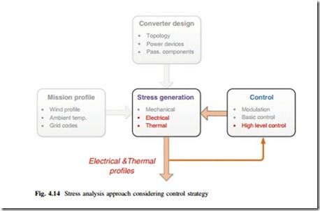
In this section, a thermal control concept which utilizes the reactive power to relive the temperature excursion under wind gust is going to be introduced. The relevant approaches for the analysis are highlighted in Fig. 4.14. It can be seen that this section mainly investigates the electrical and thermal stress influenced by the control strategy of wind power converter. It should be noted that a control loop is created by feedback the thermal stress to the control part of converter.
Control Idea and Diagram
It has been revealed that the thermal stresses in the 3L-NPC converter are quite fluctuated under the wind gust operation, which is proven to be adverse for the reliability of power devices. Because the junction temperature of the power devices is proportional to the consumed power losses, one idea to reduce the junction temperature fluctuation is to increase the device losses at the period with lower junction temperature. It is known that the consumed losses of power switching devices are governed by the delivered active and reactive power of converter. In a grid connected wind power converter, the delivered active power is set according to the input mechanical power from wind turbines and it cannot be regulated in order to maintain the DC bus voltage. As a result, the delivered reactive power is one of
the left control freedoms to change the loss and thermal behavior in the power devices.
A junction temperature control method is thereby proposed: The control target is to maintain the mean junction temperature of the most stressed device (e.g., Dnpc in the given 3L-NPC converter) at the fixed level. By adjusting the amount of reactive power delivered by the power converter, it is possible to change the device loss dissipation and thereby make the real device junction temperature trace the tem- perature reference. Consequently, the thermal excursion in the power devices can be more stabilized under wind gust.
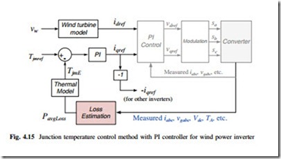
One possible control diagram is demonstrated in Fig. 4.15. For simplicity, the active current reference idref is generated by the wind speed referring to the wind turbine model. A PI controller is used to control the error between temperature reference Tjmref and the estimated junction temperature TjmE. Then the output of the PI controller is used as the reactive current reference iqref for the target converter.
It is noted that in the proposed control system shown in Fig. 4.15, a loss calculation model is important to accurately estimate the junction temperature of the target power devices in order to close the control loop. The inputs of this loss estimation block can be the real-time measured voltages, currents, and ambient temperature from the converter. More detailed explanations for the control models can be found in the attached special topic Chap. 11 and [21].
Idea to Overcome the Reactive Power Limits
Nevertheless, the controllable reactive power by wind power converter has to be restrained by grid codes, which normally define much narrower ranges of reactive power than the converter ability. As a result, the junction temperature controllability in the case of one converter is severely limited.
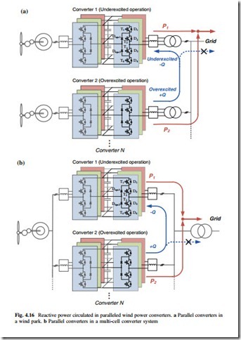
But the situation is different in the case of a wind park or a multi-cell converter system where a few converters are connected in parallel. The basic idea to over- come the range limits of reactive power by grid codes is to circulate the reactive power among the paralleled power converters, as shown in Fig. 4.16a, b, respectively. It can be seen that for the two cases the reactive power is only trapped among converters and will not be injected into the power grid. Thereby, the useable reactive power range is significantly enlarged and only limited by the device ratings.
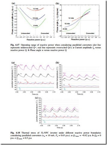
Thermal Stress Considering Extended Q Ranges in Paralleled Converters When considering the circulated reactive power among paralleled converters, the current amplitude and phase angle with relation to the delivered reactive power are plotted in Fig. 4.17a, b, respectively, in which different active power situations when the wind speed is 12 m/s (P = 1 p.u.), 10 m/s (P = 0.6 p.u.), and 8 m/s (P = 0.3 p.u.) are indicated. It can be seen that the delivered active/reactive power by the wind power converter can be dramatically enlarged compared to Fig. 4.12.
The corresponding junction temperature of the 3L-NPC converter is shown in Fig. 4.18, where the wind turbine is generating 0.63 p.u. active power at 10 m/s wind speed and three extended reactive power conditions are applied: (a) maximum underexcited reactive power when Q−max (10 m/s) = −0.82 p.u., (b) no reactive power when PF = 1, and (c) maximum overexcited reactive power when Q+max (10 m/s) = 0.5 p.u.. It can be seen that the underexcited reactive power can significantly increase the junction temperature in the most stressed devices of the given 3L-NPC converter (outer switches T1 and clamping diode Dnpc).
Thermal Control Results
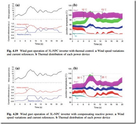
Figure 4.19 shows the thermal stress of the power devices with the same wind speed variation in Fig. 4.8a. By enabling the proposed thermal control method, in which the underexcited reactive current is adjusted to keep the average junction temper- ature in the most stressed device (Dnpc) constant when the wind speed is below m/s. It can be seen that junction thermal excursion amplitude in Dnpc reduces from 32 °C (rising edge) and 25 °C (falling edge) in Fig. 4.8b to 12 °C (rising edge) and 13 °C (falling edge), respectively in Fig. 4.19b with the proposed thermal control method.
Figure 4.20 shows the situation for the paralleled converter in Fig. 4.16 which compensates the reactive power generated by the target converter. The amount of overexcited reactive current is adjusted to compensate the underexcited reactive
power consumed by the converter 1. As a result, the overexcited reactive current reference in Fig. 4.20a has the same amplitude but opposite direction compared to Fig. 4.19a. It can be seen from Fig. 4.20b that the maximum junction temperature as well as thermal excursion of the most stressed devices is not further increased.
