Principles of operation
Since they perform the most arduous duty, circuit breakers are used here for the following brief description of switchgear operating principles.
The heart of a circuit breaker is the contact system which comprises a set of moving contacts, a set of fixed contacts, their current carrying conductors or leads and an opening mechanism which is often spring-loaded.
The fixed and moving contacts are normally made of copper, with sufficient size and cross section to carry the rated current continuously. Attached or plated onto the copper are the contact tips or faces which are of silver or an alloy. The contact tip or face is the point at which the fixed and moving contacts touch, enabling the current to flow. It is a requirement that a low contact junction resistance is maintained, and that the contacts are not welded, destroyed or unduly eroded by the high thermal and dynamic stresses of a short circuit.
As the device closes, the contact faces are forced together by spring or other kinds of pressure generated from the mechanism. This pressure is required in order to reduce the contact junction resistance and therefore the ohmic heating at the contacts; it also assists in the destruction or compaction of foreign material such as oxides which may contaminate the contact faces. The closing process is further assisted by arranging the geometry to give a wiping action as the contacts come together; the wiping helps to ensure that points of purely metallic contact are formed.
The breaking or interruption action is made particularly difficult by the formation of an arc as the contacts separate. The arc is normally extinguished as the current reaches a natural zero in the ac cycle; this mechanism is assisted by drawing the arc out to maximum length, therefore increasing its resistance and limiting the arc current. Various techniques are adopted to extend the arc; these differ according to size, rating and application and this is covered in more detail in the following sections.
The interruption of a resistive load current is not usually a problem. In this case the power factor is close to unity. When the circuit breaker contacts open, draw an arc and interrupt the current, the voltage rises slowly from its zero to its peak following its natural 50 Hz or 60 Hz shape. The build up of voltage across the opening contacts is therefore relatively gentle, and it can be sustained as the contact gap increases to its fully open point.
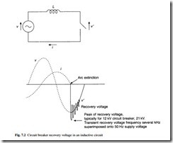
However, in many circuits the inductive component of current is much higher than the resistive component. If a short circuit occurs near the circuit breaker, not only is the fault impedance very low, and the fault current at its highest, but also the power factor may be very low, often below 0.1, and the current and voltage are nearly 90° out of phase. As the contacts open and the current is extinguished at its zero point, the voltage tends instantaneously to rise to its peak value. This is illustrated in Fig. 7.2. This results in a high rate of rise of voltage across the contacts, aiming for a peak
transient recovery voltage which is considerbly higher than the normal peak system voltage. There is a risk under these circumstances that the arc will re-strike even though the contacts are separating, and the design of the circuit breaker must take this into account.
