Charging systems
The charging system restores the energy depleted from the battery during cranking and provides power to operate lights and other accessories. It consists of two major components: an alternator and a regulator. The circuit can be monitored by an ammeter or a lamp and is usually fused to protect the generator windings.
Alternators generate a high frequency 3-phase AC voltage, which is rectified (i. e., converted to direct current) by internal diodes. Wrong polarity will destroy the diodes and can damage the wiring harness. Observe the polarity when installing a new battery or when using jumper cables. Before connecting a charger to the battery, disconnect the cables. Should the engine be started with the charger in the circuit the regulator might be damaged. Isolate the charging system before any arc welding is done. Do not disconnect the battery or any other wiring while the alter- nator is turning. And, finally, do not attempt to polarize an alternator. The exercise is fruitless and can destroy diodes.
Initial tests
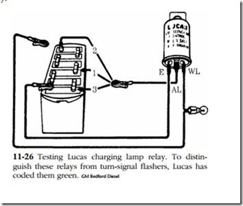
The charge light should be on with the switch on and the engine stopped. Failure to light indicates an open connection in the bulb itself or in the associated wiring. Most charging-lamp circuits operate by a relay under the voltage regulator cover. Lucas systems employ a separate relay that responds to heat. The easiest way to check either type is to insert a 0–100A ammeter in series with the charging circuit. If the meter shows current and the relay does not close, one can safely assume that it has failed and should be replaced. The Lucas relay can be tested as shown in Fig. 11-26. You will need a voltage divider and 2.2W lamp. Connect clip A to the 12V terminal. The lamp should come on. Leaving the 12V connection in place, connect clip B to the 6V tap. The bulb should burn for 5 seconds or so and go out. Move B to the 12V post and hold for no more than 10 seconds. Then move it to the 2V (single cell) tap. The bulb should come on within 5 seconds. These units do not have computerlike precision, and some variation can be expected between them. But the test results should roughly correlate with the test procedure. Do not attempt to repair a suspect relay.
Test the alternator output against the meter on the engine or by inserting a test meter in series between the B terminal and battery. Voltage is monitored with a meter in parallel with the charging circuit. Discharge the battery by switching on the lights and other accessories. Connect a rheostat or carbon pile across the battery for a con- trolled discharge. (Without this tool you will be reduced to guessing about alternator condition.) With the load set at zero, start the engine and operate at approximately midthrottle. Apply the load until the alternator produces its full rated output. If necessary open the throttle wider. An output 2–6A below rating often means an open diode. Ten amps or so below rating usually means a shorted diode. The alternator might give further evidence of a diode failure by whining like a wounded banshee.
The voltage should be 18–20V above the nominal battery voltage under normal service conditions. It might be higher by virtue of automatic temperature compensation in cold weather.
Assuming that the output is below specs, the next step is to isolate the alternator from the regulator. Disconnect the field (F or FD) terminal from the regulator and ground it to the block. Load the circuit with a carbon pile to limit the voltage out-put. Run the engine at idle. In this test we have dispensed with the regulator and are protecting the alternator windings with carbon pile. No appreciable output difference between this and the previous tests means that the regulator is doing its job. A large difference would indicate that the regulator was defective.
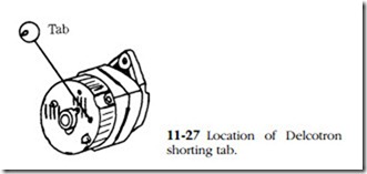
Late-production alternators often have integrated regulators built into the slip ring end of the unit. Most have a provision for segregating alternator output from the reg- ulator so that “raw” outputs can be measured. The Delcotron features a shorting tab. A screwdriver is inserted into an access hole in the back of the housing (Fig. 11-27); contact between the housing and the tab shorts the fields.
Note : The tab is within 3/4 in. of the casting. Do not insert a screwdriver more than 1 in. into the casting.
Bench testing
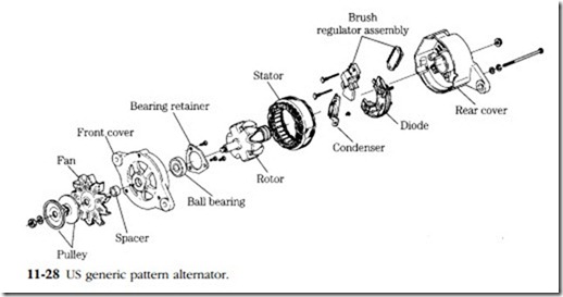
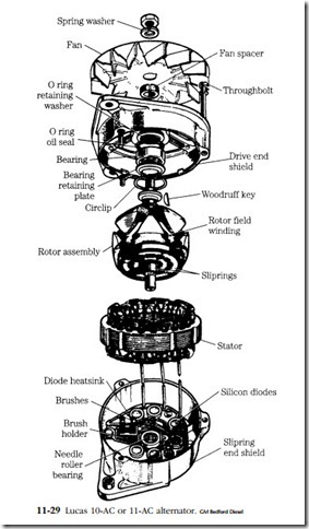
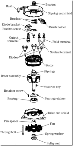
Disconnect the battery and remove the alternator from the engine at the pivot and belt-tensioning bracket. Three typical alternators are shown in exploded view in Figs. 11-28 through 11-30.
Remove the drive pulley. A special tool might be needed on some of the auto- motive derivations. Hold the fan with a screwdriver and turn the fan nut counter- clockwise. Tap the sheave and fan off the shaft with a mallet. Remove the throughbolts and separate the end shields.
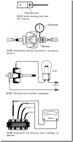
Inspect the brushes for wear. Some manufacturers thoughtfully provide a wear limit line on the brushes (Fig. 11-31). Clean the holders with Freon or some other non-petroleum-based solvent and check the brushes for ease of movement. File lightly if they appear to bind. The slip rings should be miked for wear and eccentricity. Ten to twelve thousandths should be considered the limit (Fig. 11-32). Slip rings are usually, but not always, integral with the rotor. Removable rings are chiseled off and new ones pressed into place. Fixed rings can be restored to concentricity with light machining.
Determine the condition of the rotor insulation with a 120V test lamp (Fig. 11-33). The slip rings and their associated windings should be insulated from the shaft and pole pieces. If you have access to an accurate, low-range ohmmeter, test for continuity between slip rings. The resistance might lead one to suspect a partial open; less could mean an intracoil short.
The stator consists of three distinct and independent windings whose outputs are 120° apart. It is possible for one winding to fail without noticeably affecting the others. Peak alternator output will, of course, be reduced by one third. Disconnect the three leads going to the stator windings. Many European machines have these leads soldered, while American designs generally have terminal lugs. When unsoldering, be extremely careful not to overheat the diodes. Exposure to more than 300°F will upset their crystalline structure. Test each winding for resistance. Connect a low-range ohmmeter between the natural lead and each of three winding leads as shown in Fig. 11-34. Resistance will be quite low—on the order of 5 or 6 fl—and becomes critical when one group of windings gives a different reading than the others.
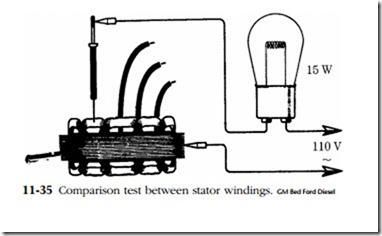
Test the stator insulation with a 120V lamp connected as shown in Fig. 11-35. There should be no continuity between the laminations and windings.
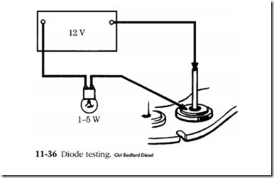
The next step is to check the diodes (Fig. 11-36). You might already have had some evidence of diode trouble in the form of alternator whine or blackened varnish on the stator coils. The diodes must be tested with an ohmmeter or a test lamp of the same voltage as generator output.
Test each diode by connecting the test leads and then reversing their polarity. The lamp should light in one polarity and go out in the other. Failure to light at all means an open diode; continuous burning means the diode has shorted. In either case it must be replaced. You might use a low-voltage ohmmeter in lieu of a lamp.
Prestolite CAB-1235 or CAB-1245 alternator. GM Bedford Diesel Expect high (but not infinite) resistance with one connection, and low (but not zero) resistance when the two leads are reversed.
To simply service and limit the need for special tools, some manufacturers pack- age mounting brackets with their diodes. The bracket is a heat sink and must be in intimate contact with the diode case. Other manufacturers take the more traditional approach and supply individual diodes, which must be pressed (not hammered) into
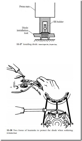
their sinks. K-D Tools makes a complete line of diode removal and installation aids, including heat sink supports and diode arbors of various diameters. Figure 11-37 shows a typical installation with an unsupported heat sink. Other designs might require support.
Soldering the connections is very critical. Should the internal temperature reach 300°F the diode will be ruined. Use a 150W or smaller iron and place a thermal shunt between the soldered joint and the diode (Fig. 11-38). The shunt might be in the form of a pair of needle-nosed pliers or copper alligator clips. In some instances there might not be room to shunt the heat load between the diode and joint (Fig. 11-38) It is only necessary to twist the leads enough to hold them while the solder is liquid. Work quickly and use only enough solder to flow between the leads. More solder merely increases the thermal load and increases the chances that the diode will be ruined.
Alternator bearings are sealed needle and ball types. They are not to be disturbed unless noisy or rough. Then bearings are pressed off and new ones installed with the numbered end toward the arbor.
