Introduction
Safety is critically important to engineering personnel who work around powered hardware, especially if they work under considerable time pressures. Safety is not something to be taken lightly. Life safety systems are those designed to protect life and property. Such systems include emergency lighting, fire alarms, smoke exhaust and ventilating fans, and site security.
Facility Safety Equipment
Personnel safety is the responsibility of the facility manager. Proper life safety procedures and equipment must be installed. Safety-related hardware includes the following:
• Emergency power off (EPO) button. EPO pushbuttons are required by safety code for various types of facilities, including data processing (DP) centers. One must be located at each principal exit from the room. Other EPO buttons may be located near operator workstations. The EPO system, intended only for emergencies, disconnects all power to the room, except for lighting.
• Smoke detector. Two basic types of smoke detectors commonly are available. The first compares the transmission of light through air in the room with light through a sealed optical path into which smoke cannot penetrate. Smoke causes a differential or backscattering effect that, when detected, triggers an alarm after a preset threshold has been exceeded. The second type of smoke detector senses the ionization of combustion products rather than visible smoke. A mildly radioactive source, usually nickel, ionizes the air passing through a screened chamber. A charged probe captures ions and detects the small current that is proportional to the rate of capture. When combustion products or material other than air molecules enter the probe area, the rate of ion production changes abruptly, generating a signal that triggers the alarm.
• Flame detector. The flame sensor responds not to heated surfaces or objects, but to infrared when it flickers with the unique characteristics of a fire. Such detectors, for example, will respond to a lighted match, but not to a cigarette. The ultraviolet light from a flame also is used to distinguish between hot, glowing objects and open flame.
• Halon. The Halon fire-extinguishing agent is a low-toxicity, compressed gas that is contained in pressurized vessels. Discharge nozzles in data processing rooms and other types of equipment rooms are arranged to dispense the entire contents of a central container or of multiple smaller containers of Halon when actuated by a command from the fire control system. The discharge is sufficient to extinguish flame and stop combustion of most flammable substances. Halon is one of the more common fire-extinguishing agents used for DP applications. Halon systems usually are not practical, however, in large, open-space facilities.
• Water sprinkler. Although water is an effective agent against a fire, activation of a sprinkler system will often cause damage to the equipment it is meant to protect. Interlock systems must drop all power (except for emergency lighting) before the water system is discharged. Most water systems use a two-stage alarm. Two or more fire sensors, often of different design, must signal an alarm condition before water is discharged into the protected area. Where sprinklers are used, floor drains and EPO controls must be provided.
• Fire damper. Dampers are used to block ventilating passages in strategic parts of the system when a fire is detected. This prevents fire from spreading through the passages and keeps fresh air from fanning the flames. A fire damper system, combined with the shutdown of cooling and ventilating air, enables Halon to be retained in the protected space until the fire is extinguished.
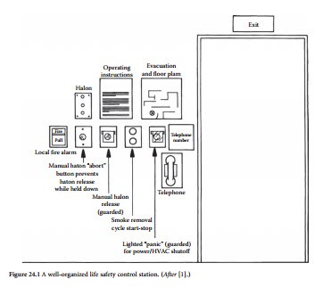
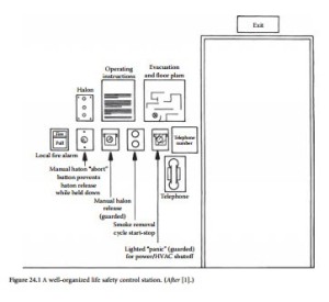
Many life safety system functions can be automated. The decision of what to automate and what to operate manually requires considerable thought. If the life safety control panels are accessible to a large number of site employees, most functions should be automatic. Alarm-silencing controls should be maintained under lock and key. A mimic board can be used to readily identify problem areas. Figure illustrates a well-organized life safety control system. Note that fire, HVAC (heating, ventilation, and air-conditioning), security, and EPO controls all are readily accessible. Note also that operating instructions are posted for life safety equipment, and an evacuation route is shown. Important telephone numbers are posted, and a direct-line telephone (not via the building switchboard) is provided. All equipment is located adjacent to a lighted emergency exit door.
Life safety equipment must be maintained just as diligently as the systems that it protects. Conduct regular tests and drills. It is, obviously, not necessary or advisable to discharge Halon or water during a drill.
Configure the life safety control system to monitor not only the premises for dangerous conditions, but also the equipment designed to protect the facility. Important monitoring points include HVAC
machine parameters, water or Halon pressure, emergency battery-supply status, and other elements of the system that could compromise the ability of life safety equipment to carry out its functions. Basic guidelines for life safety systems include the following:
• Carefully analyze the primary threats to life and property within the facility. Develop contingency plans to meet each threat.
• Prepare a life safety manual, and distribute it to all employees at the facility. Require them to read it.
• Conduct drills for employees at random times without notice. Require acceptable performance from employees.
• Prepare simple, step-by-step instructions on what to do in an emergency. Post the instructions in a conspicuous place.
• Assign after-hours responsibility for emergency situations. Prepare a list of supervisors that oper- ators should contact if problems arise. Post the list with phone numbers. Keep the list accurate and up-to-date. Always provide the names of three individuals who can be contacted in an emergency.
• Work with a life safety consultant to develop a coordinated control and monitoring system for the facility. Such hardware will be expensive, but it must be provided. The facility may be able to secure a reduction in insurance rates if comprehensive safety efforts can be demonstrated.
• Interface the life safety system with automatic data-logging equipment so that documentation can be assembled on any event.
• Insist upon complete, up-to-date schematic diagrams for all hardware at the facility. Insist that the diagrams include any changes made during installation or subsequent modification.
• Provide sufficient emergency lighting.
• Provide easy-access emergency exits.
The importance of providing standby power for sensitive loads at commercial and industrial facili- ties has been outlined previously. It is equally important to provide standby power for life safety systems. A lack of ac power must not render the life safety system inoperative. Sensors and alarm control units should include their own backup battery supplies. In a properly designed system, all life safety equipment will be fully operational despite the loss of all ac power to the facility, including backup power for sensitive loads.
Place cables linking the life safety control system with remote sensors and actuators in separate conduit containing only life safety conductors. Study the National Electrical Code and all applicable local and federal codes relating to safety. Follow them to the letter.
Electric Shock
It takes surprisingly little current to injure a person. Studies at Underwriters Laboratories (UL) show that the electrical resistance of the human body varies with the amount of moisture on the skin, the muscular structure of the body, and the applied voltage. The typical hand-to-hand resistance ranges from 500 Ω to 600 kΩ, depending on the conditions. Higher voltages have the capability to break down the outer layers of the skin, which can reduce the overall resistance value. UL uses the lower value, 500 Ω, as the standard resistance between major extremities, such as from the hand to the foot. This value generally is considered the minimum that would be encountered. In fact, it may not be unusual because wet conditions or a cut or other break in the skin significantly reduces human body resistance.
Effects on the Human Body
Table 24.1 lists some effects that typically result when a person is connected across a current source with a hand-to-hand resistance of 2.4 kΩ. The table shows that a current of 50 mA will flow between the hands, if one hand is in contact with a 120 V ac source and the other hand is grounded. The table also indicates that even the relatively small current of 50 mA can produce ventricular fibrillation of the heart, and
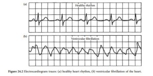
maybe even cause death. Medical literature describes ventricular fibrillation as very rapid, uncoordinated contractions of the ventricles of the heart, resulting in loss of synchronization between heartbeat and pulse beat. The electrocardiograms shown in Figure 24.2 compare a healthy heart rhythm with one in ventricular fibrillation. Unfortunately, once ventricular fibrillation occurs, it will continue. Barring resuscitation techniques, death will ensue within a few minutes.
The route taken by the current through the body greatly affects the degree of injury. Even a small current, passing from one extremity through the heart to another extremity, is dangerous and capable of causing severe injury or electrocution. There are cases in which a person has contacted extremely high current levels and lived to tell about it. However, when this happens, it is usually because the current passes only through a single limb and not through the entire body. In these instances, the limb is often lost but the person survives.
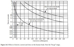
Current is not the only factor in electrocution. Figure 24.3 summarizes the relationship between current and time on the human body. The graph shows that 100 mA flowing through an adult human body for 2 s will cause death by electrocution. An important factor in electrocution, the let-go range, also is shown on the graph. This point marks the amount of current that causes freezing, or the inability to let go of a conductor. At 10 mA, 2.5% of the population would be unable to let go of a live conductor; at 15 mA, 50% of the population would be unable to let go of an energized conductor. It is apparent from the graph that even a small amount of current can freeze someone to a conductor. The objective for those
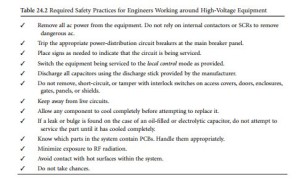
who must work around electric equipment is to protect themselves from electric shock. Table 24.2 lists required precautions for maintenance personnel working near high voltages.
Circuit-Protection Hardware
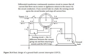
A common primary panel or equipment circuit breaker or fuse will not protect an individual from electrocution. However, the ground-fault current interrupter (GFCI), used properly, can help prevent electro- cution. Shown in Figure 24.4, the GFCI works by monitoring the current being applied to the load. It
Differential transformer continuously monitors circuit to ensure that all current that flows out to motor or appliances returns to the source via the circuit conductors. If any current leaks to a fault, the sensing circuit opens the circuit breaker and stops all current flow.
uses a differential transformer that senses an imbalance in load current. If a current (typically 5 mA, ± 1 mA on a low-current 120 V ac line) begins flowing between the neutral and ground or between the hot and ground leads, the differential transformer detects the leakage and opens the primary circuit (typically within 2.5 ms).
Occupational Safety and Health Administration (OSHA) rules specify that temporary receptacles (those not permanently wired) and receptacles typically used on construction sites be equipped with GFCI protection. Receptacles on two-wire, single-phase portable and vehicle-mounted generators of not more than 5 kW, where the generator circuit conductors are insulated from the generator frame and all other grounded surfaces, need not be equipped with GFCI outlets.
GFCIs will not protect a person from every type of electrocution. If you become connected to both the neutral and the hot wire, the GFCI will treat you as if you are merely a part of the load and will not open the primary circuit.
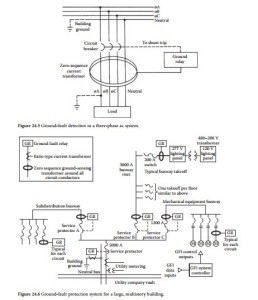
For large, three-phase loads, detecting ground currents and interrupting the circuit before injury or damage can occur is a more complicated proposition. The classic method of protection involves the use of a zero-sequence current transformer (CT). Such devices are basically an extension of the single-phase GFCI circuit shown in Figure 24.4. Three-phase CTs have been developed to fit over bus ducts, switch- board buses, and circuit-breaker studs. Rectangular core-balanced CTs are able to detect leakage currents as small as several milliamperes when the system carries as much as 4 kA. “Doughnut-type” toroidal zero-sequence CTs also are available in varying diameters.
The zero-sequence current transformer is designed to detect the magnetic field surrounding a group of conductors. As shown in Figure 24.5, in a properly operating three-phase system, the current flowing through the conductors of the system, including the neutral, goes out and returns along those same con- ductors. The net magnetic flux detected by the CT is zero. No signal is generated in the transformer winding, regardless of current magnitudes — symmetrical or asymmetrical. If one phase conductor is faulted to ground, however, the current balance will be upset. The ground-fault-detection circuit then will trip the breaker and open the line.
For optimum protection in a large facility, GFCI units are placed at natural branch points of the ac power system. It is, obviously, preferable to lose only a small portion of a facility in the event of a ground fault than it is to have the entire plant dropped. Figure 24.6 illustrates such a distributed system. Sensors are placed at major branch points to isolate any ground fault from the remainder of the distribution net- work. In this way, the individual GFCI units can be set for higher sensitivity and shorter time delays than would be practical with a large, distributed load. The technology of GFCI devices has improved
significantly within the past few years. New integrated circuit devices and improved CT designs have pro- vided improved protection components at a lower cost.
Sophisticated GFCI monitoring systems are available that analyze ground-fault currents and isolate the faulty branch circuit. This feature prevents needless tripping of GFCI units up the line toward the utility service entrance. For example, if a ground fault is sensed in a fourth-level branch circuit, the GFCI system controller automatically locks out first-, second-, and third-level devices from operating to clear the fault. The problem, therefore, is safely confined to the fourth-level branch. The GFCI control system is designed to operate in a fail-safe mode. In the event of a control-system shutdown, the individual GFCI trip relays would operate independently to clear whatever fault currents may exist.
Any facility manager would be well-advised to hire an experienced electrical contractor to conduct a full ground-fault protection study. Direct the contractor to identify possible failure points and to recom- mend corrective actions.
An extensive discussion of GFCI principals and practices can be found in Reference 2.
Working with High Voltage
Rubber gloves are a common safety measure used by engineers working on high-voltage equipment. These gloves are designed to provide protection from hazardous voltages when the wearer is working on “hot” circuits. Although the gloves may provide some protection from these hazards, placing too much reliance on them poses the potential for disastrous consequences. There are several reasons why gloves should be used only with a great deal of caution and respect. A common mistake made by engineers is to assume that the gloves always provide complete protection. The gloves found in some facilities may be old and untested. Some may even have been “repaired” by users, perhaps with electrical tape. Few tools could be more hazardous than such a pair of gloves.
Know the voltage rating of the gloves. Gloves are rated differently for ac and dc voltages. For instance, a class 0 glove has a minimum dc breakdown voltage of 35 kV; the minimum ac breakdown volt- age, however, is only 6 kV. Furthermore, high-voltage rubber gloves are not tested at RF frequencies, and RF can burn a hole in the best of them. Working on live circuits involves much more than simply wearing a pair of gloves. It involves a frame of mind — an awareness of everything in the area, especially ground points.
Gloves alone may not be enough to protect an individual in certain situations. Recall the axiom of keeping one hand in your pocket while working on a device with current flowing? The axiom actually is based on simple electricity. It is not just the hot connection that causes the problem; it is the ground con- nection that permits current flow. Studies have showed that more than 90% of electric equipment fatali- ties occurred when the grounded person contacted a live conductor. Line-to-line electrocution accounted for less than 10% of the deaths.
When working around high voltages, always look for grounded surfaces — and keep away from them. Even concrete can act as a ground if the voltage is high enough. If work must be conducted in live cabinets, consider using — in addition to rubber gloves — a rubber floor mat, rubber vest, and rubber sleeves. Although this may seem to be a lot of trouble, consider the consequences of making a mistake. Of course, the best troubleshooting methodology is never to work on any circuit unless you are sure no haz- ardous voltages are present. In addition, any circuits or contactors that normally contain hazardous volt- ages should be grounded firmly before work begins.
Another important safety rule is to never work alone. Even if a trained assistant is not available when maintenance is performed, someone should accompany you and be available to help in an emergency.
First Aid Procedures
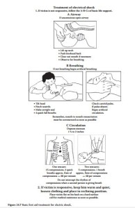
Be familiar with first aid treatment for electric shock and burns. Always keep a first aid kit on hand at the facility. Figure 24.7 illustrates the basic treatment for electric shock victims. Copy the information, and post it in a prominent location. Better yet, obtain more detailed information from your local heart asso- ciation or Red Cross chapter. Personalized instruction on first aid usually is available locally. Table 24.3 lists basic first aid procedures for burns.
For electric shock, the best first aid is prevention. In the event that an individual has sustained or is sustaining an electric shock at the work place, several guidelines are suggested, as detailed next.
Shock in Progress
For the case when a co-worker is receiving an electric shock and cannot let go of the electrical source, the safest action is to trip the circuit breaker that energizes the circuit involved, or to pull the power-line plug on the equipment involved if the latter can be accomplished safely [2]. Under no circumstances should the rescuer touch the individual who is being shocked, because the rescuer’s body may then also be in the dangerous current path. If the circuit breaker or equipment plug cannot be located, then an attempt can be made to separate the victim from the electrical source through the use of a nonconducting object such as a wooden stool or a wooden broom handle. Use only an insulating object and nothing that contains metal or other electrically conductive material. The rescuer must be very careful not to touch the victim or the electrical source and thus become a second victim.
If such equipment is available, hot sticks used in conjunction with lineman’s gloves may be applied to push or pull the victim away from the electrical source. Pulling the hot stick normally provides the greatest control over the victim’s motion and is the safest action for the rescuer. After the electrical source has been turned off, or the victim can be reached safely, immediate first aid procedures should be implemented.
Shock No Longer in Progress
If the victim is conscious and moving about, have the victim sit down or lie down. Sometimes there is a delayed reaction to an electrical shock that causes the victim to collapse. Call 911 or the appropriate plant-site paramedic team immediately. If there is a delay in the arrival of medical personnel, check for electrical burns. In the case of severe shock, there will normally be burns at a minimum of two sites: the entry point for the current and the exit point(s). Cover the burns with dry (and sterile, preferably) dress- ings. Check for possible bone fractures if the victim was violently thrown away from the electrical source and possibly impacted objects in the vicinity. Apply splints as required if suitable materials are available and you have appropriate training. Cover the victim with a coat or blanket if the environmental temperature is below room temperature, or the victim complains of feeling cold.
If the victim is unconscious, call 911 or the appropriate plant-site paramedic team immediately. In the interim, check to see if the victim is breathing and if a pulse can be felt at either the inside of a wrist above the thumb joint (radial pulse) or in the neck above and to either side of the Adam’s apple (carotid pulse). It is usually easier to feel the pulse in the neck as opposed to the wrist pulse, which may be weak. The index and middle finger should be used to sense the pulse, and not the thumb. Many individuals have an apparent thumb pulse that can be mistaken for the victim’s pulse. If a pulse can be detected but the victim is not breathing, begin mouth-to-mouth respiration if you know how to do so. If no pulse can be detected (presumably the victim will not be breathing), carefully move the victim to a firm surface and begin cardiopulmonary resuscitation if you have been trained in the use of CPR. Respiratory arrest and cardiac arrest are crisis situations. Because of loss of the oxygen supply to the brain, permanent brain damage can occur after several minutes even if the victim is successfully resuscitated.
Ironically, the treatment for cardiac arrest induced by an electric shock is a massive countershock, which causes the entire heart muscle to contract. The random and uncoordinated ventricular fibrillation contractions (if present) are thus stilled. Under ideal conditions, normal heart rhythm is restored once the shock current ceases. The countershock is generated by a cardiac defibrillator, various portable mod- els of which are available for use by emergency medical technicians and other trained personnel. Although portable defibrillators may be available at industrial sites where there is a high risk of electrical shock to plant personnel, they should be used only by trained personnel. Application of a defibrillator to an unconscious subject whose heart is beating can induce cardiac standstill or ventricular fibrillation, just the conditions that the defibrillator was designed to correct.
