Measure of Control of Communication-Betweenness Centrality
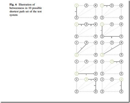
This type of centrality is based upon the frequency with which a node falls between pairs of other nodes on the shortest or geodesic paths connecting them [3]. This idea is illustrated by 10 possible shortest paths in the network of Fig. 1 as shown in Fig. 6. Node 2 comes four times between other points in the six geodesics. Node 4 comes three times. So node 2 is more central in terms of betweenness.
The betweenness centrality CBðkÞ for vertex k is computed as follows [21]:
1. Find the shortest path set of the network.
2. Find out the fraction of the shortest path containing node k for each pair of vertices.
3. Sum this fraction over all pairs.
where, rst is the number of shortest paths from s to t, and rst ðkÞ is the number of shortest paths from s to t that pass through a vertex k.
As in closeness centrality the shortest paths for an electrical network can be calculated from the line impedance, and the power flowing in the line is taken as a measure of betweenness [14]. The electrical betweenness centrality of a node k in a network of n nodes is defined as:
where, Pst is the maximum power flowing in the shortest electrical path between buses s and t, and PstðkÞ is the maximum of inflow and outflow at bus k within the shortest electrical path between buses s and t. Figure 7 illustrates the concept of electrical shortest path and shows 10 possible geodesics in the simple 5 bus test system.
Table 4 shows the betweenness centrality of simple 5 bus system in Fig. 1 using classical and proposed approach (Tables 5, 6, and 7).


