PF Testing of Electrical Apparatus Insulation
PF testing is normally used for acceptance testing, preventing maintenance, and post maintenance insulation assessment, and for condition trending. The test voltage used for PF testing should be sufficient to detect any latent weaknesses in the insulation, but since the test is intended to be nondestruc- tive, the voltage should not exceed normal line-to-neutral or line-to-ground operating voltage of the apparatus under test. Below, the PF testing of various electrical apparatus and equipment is discussed.
Transformers
Power and distribution transformers may be either single-phase or three- phase and may be either dry-type, or oil or synthetic-liquid filled. Transformers may be installed indoors or outdoors depending upon application. The PF test as applied to transformers is the most comprehensive test for detecting insulation degradation, usually caused by moisture, carbonization, and other forms of contamination. Depending on the type, size, and voltage rating of transformer, the PF test may be performed as an overall transformer PF test, or on individual components of the transformer to localize the dielectric cir- cuit for effective analysis of the test results; that is deterioration in the solid winding, bushing, and liquid insulation can be localized by separate tests on these components. Generally, it is common practice to perform PF tests of the bushing and the solid winding together on medium-voltage transformers that have solid porcelain-type bushings. On HV transformers with condenser-type bushings, the PF tests are performed on the individual bushings by the UST method. On all other bushings, hot-collar tests are performed by the GST method.
The types of transformers considered for the purposes of PF testing are
1. Two-winding transformers
2. Three-winding transformers
3. Autotransformers
4. Potential transformers (PTs)
When performing PF tests on transformers, the below listed conditions should be observed:
1. Transformer is de-energized and completely isolated from the power source.
2. Transformer housing is properly grounded.
3. All bushing of HV and LV winding, including the neutral are shorted to make them into an equivalent HV and LV bushings. Neutrals must be ungrounded.
4. Transformers equipped with load-tap-changers should be set to some position off neutral, and this position should be noted on the test data sheet.
Two-Winding Transformers
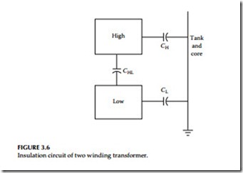
In a three-phase or a single-phase two-winding transformer, the transformer winding insulation system comprises of three insulation system; that is, CH HV winding insulation, CL LV winding insulation, and CHL high-to-low winding insulation. The three insulation systems are shown in Figure 3.6.
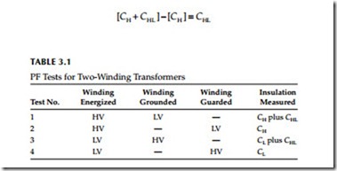
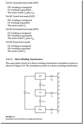
When performing PF tests, the HV bushing of the three phase units are shorted together to make them into an equivalent single bushing. Similarly, the LV bushing of three phase unit are also shorted together to make them into an equivalent bushing. Four PF tests of the windings are made as shown in Table 3.1. As shown in the Table 3.1, results of test 1 minus test 2, and test 3 minus test 4 are calculated to validate that the PF test have been made correctly.
Calculated results of Table 3.1: test 1 minus test 2
1. Subtract charging current of test 2 from test 1
2. Subtract watt loss of test 2 from test 1
3. Then calculate the PF, that is
[CH + CHL ] − [CH ] = CHL
The calculated value of CHL from the above calculation should be same. If it is not then there is either an error in the test results or the calculated results.
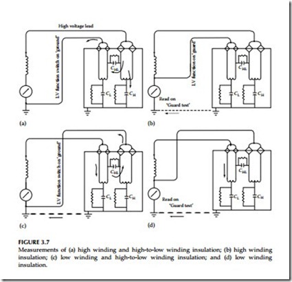
The test connection arrangements for each of the four tests listed in the Table 3.1 are described below in Figure 3.7a through d.


