Selection of Multilevel Converter Topology
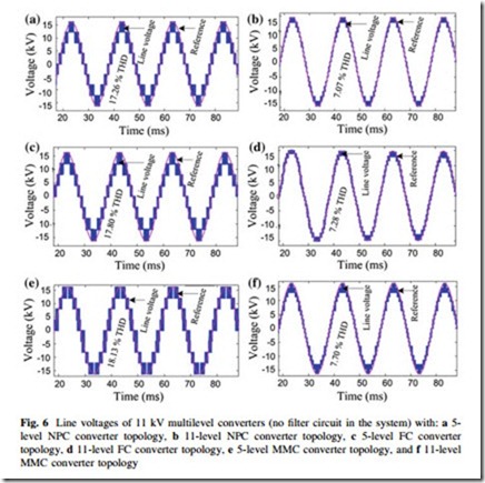
The main aim of this section is to find out a suitable converter topology, which can interconnect the renewable generation units to the grid directly by using mature semiconductor technology. A 5-level NPC, a 5-level FC, a 5-level MMC, an 11- level NPC, an 11-level FC, and an 11-level MMC converter topologies are considered for the comparison. The comparison is made in terms of number of semiconductors, semiconductor cost, THDs, filter size, and control complexity of the converters. The performance is analyzed and compared in the MATLAB environment. To generate switching pulses a level-shifted carriers-based switching scheme is used for NPC topologies and a phase-shifted carriers-based switching scheme is used for FC and MMC converter topologies with a carrier frequency of 1 to 2 kHz and modulation index of 0.8 to 0.90. The output voltage waveforms are shown in Fig. 6.
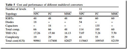
The output voltage waveform of 5-level NPC converter much more coincides with the reference sine wave as compared with other 5-level converters outputs. All 11-level converters output voltage waveforms are very close to the reference sine wave while NPC converter performance is better than the others. Moreover, from the output figures it is clear that increasing the level numbers means improving the converter performance. It is assumed that each blocking diode voltage rating is the same as the active device voltage rating. A total of 90 diodes are required for each phase of an 11-level NPC converter. This large number of diodes affects the reverse recovery of the clamping diodes which is a major design challenge in high voltage high-power systems. A list of the number of power components required for each converter topology is summarized in Table 5. As already stated, the availability of IGBT and diode modules is also considered when designing the converter. For the 5-level NPC, FC, and MMC converter topology, each IGBT switch is formed from the series connection of two 4.5 kV IGBTs so
the number of IGBTs is 48. To enable a converter output phase current of 250 A, the simulation result is used to determine the current rating of the power semiconductors.
A total of 45 clamping capacitors are required for each phase of the 11-level FC converter. These large numbers of heavy and large size capacitors increase the converter size and cost and reduce the overall lifetime of the converter. The capacitor voltage balancing problem also becomes a challenging issue with this high level of component numbers. There are no blocking diodes or clamping capacitors in the MMC converter topology. The component numbers of this topology scale linearly with the number of levels. Hence, the overall number of components is much lower than that with other multilevel converter topologies. The individual modules are similar and totally modular in construction, which makes it easy to implement for any number of levels. The higher number of attainable levels provides more scope for reducing harmonics. The high number of levels means that it is possible to connect the converter to the medium voltage grid directly.
Table 5 also summarizes the THDs for different multilevel converter topologies. Among these three converter topologies, the NPC converter topology has the best harmonic performance. The harmonic performance of the MMC converter topology is not as good as that of the NPC converter topology. The harmonic content decreases rapidly with increasing number of levels. This means that by increasing the levels of the converter, it is possible to keep the output voltage total harmonic distortion to less than, or equal to 5 % (according to IEEE1547 and IEC61727). Among these converters, the 11-level MMC converter is the low cost high performance converter and it is suitable for the connection of medium voltage grid directly. The price data quoted for the semiconductor devices and capacitors were collected from the Galco Industrial Electronics and Farnell catalogs where devices were chosen from the same family so that it was possible to fit with requirements. The IGBTs chosen are with integrated freewheel diodes and hence these diodes do not appear in costing. The current rating of most devices is selected on the basis of simulation results.
Table 5 also summarized the estimated cost of different converter topologies. The number of semiconductors increases with the number of levels but the vari- ation in cost is small because the price of the lower rated device is comparatively
much lower. Because of the lower voltage and current requirements, the total semiconductor cost of the 11-level MMC converter is lower than that of all other topologies. The number of arithmetic and logic operations (ALOs) for switching section is calculated through the MATLAB/Simulink environment. The number of ALOs is used to compare the complexity of the converters, as summarized in Table 5.
Based on the performance, control complexity, and semiconductor cost, an overall comparative study is carried out among the converter topologies. If y is the given value, ymin the minimum value, and ymax the maximum value in a group of data, the normalized index value can be calculated as
Table 6 summarizes the index values of Table 5. For lower level number converters NPC converter topology may be the best choice. But for higher level number converters MMC converter topology may be the best choice. Moreover, in MMC converter the individual modules are identical and completely modular in construction. Thus, in the case of a fault in one of these modules, it is possible to replace it quickly and easily. Therefore, MMC is the proper converter topology to design a medium voltage converter for step-up transformer-less direct grid connection of renewable generation systems.


