Equipment installation
The code of practice for the installation of hazardous area electrical equipment is BS EN 60079-14 (reference 15R). The guidance in this code of practice is additional to the requirements for non-hazardous area installations. Electrical equipment should, preferably, be located outside a hazardous area or in the lowest risk area available. It should be installed in accordance with its documentation, including any special requirements denoted by the letter ‘X’ at the end of the certificate number. It should also be operated within all of its ratings.
The installation should be designed to protect the equipment from adverse environ- mental influences which could jeopardize the method of protection; these include temperature extremes, corrosion, mechanical damage and vibration. Electrical equip- ment, such as pressure transmitters and temperature sensors, connected directly to the process, may become filled with process fluid under failure conditions. The instal- lation of the wiring system should include, for example, impervious barriers to prevent the process material migrating through the wiring system into other areas. The installation should also be designed with regard to ease of inspection and maintenance (see section 15.8). Portable, transportable and temporary equipment should also be suitable for the zone of use.
Protection from sparking
Fault currents cause potential differences between different parts of an electrical instal- lation and plant structure. Although non-hazardous area electrical installation practices minimize these to levels which are not an electrical shock risk, they can be sufficient to create ignition-capable sparking. Consequently equipotential bonding has particular guidance. Only TN-S, TT and IT power distribution systems are recommended for hazardous area use and specific guidance is given for each. SELV and PELV systems may also be used (see section 16.2.2.4).
Other equipotential bonding systems such as those provided for lightning protection, control of static charging, electromagnetic compatibility may also exist in, or associ- ated with, hazardous areas. These should be connected together at one point to minimize potential difference between them. Cathodic protection is not normally suitable for use in hazardous areas.
Electrical protection
In most cases the electrical protection provided for the same installation in a non- hazardous area is suitable but there are a number of significant exceptions. Specific guidance is given for rotating electrical machines and transformers which includes overload protection. Multi-phase equipment should be protected against loss of one or more phases. Auto-reclosing protection is not recommended.
Means of isolation
Residual neutral voltages may be ignition-capable so, the means of isolation should also isolate the neutral.
Wiring systems
The following aspects of wiring systems have specific guidance:
|
● |
Aluminium conductors |
● |
Mechanical damage |
|
● |
Non-sheathed single cores |
● |
Electrical connections |
|
● |
Unused openings in enclosures |
● |
Migration and accumulation of |
|
● |
Circuits traversing hazardous areas |
flammable materials |
|
|
● |
Openings in walls etc. |
● |
Fortuitous contact |
|
● |
Protection of stranded conductor ends |
● |
Cable jointing |
|
● |
Overhead lines |
● |
Unused cores |
|
● |
Cable surface temperature |
Cable types for Zones 1 and 2 are mineral-insulated metal sheathed cables and ther- moplastic, thermosetting or elastomeric sheathed cables. Especially robust cable types are recommended for portable and transportable equipment, and where flexibility is required. Conduit systems may be used and specific guidance is given on stopping boxes, fault currents, corrosion, non-sheathed single conductors, condensation drains and IP ratings.
Flameproof equipment
Five additional pieces of guidance are given for flameproof equipment all of which can nullify the method of protection if not carried out.
Solid obstacles
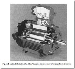
The safety of a flameproof enclosure relies on the products of combustion emerging from the enclosure not igniting a surrounding flammable atmosphere. The maximum gap between parts of a flameproof enclosure is specified in the flameproof standard as a fraction of the MESG. Such gaps, having specified maximum dimensions, are known as flamepaths and may be in the form of flanges, spigots, shafts or screw threads. The length of the flamepaths necessary in flanges and spigots is indicated in the sec- tional illustration of an EEx‘d’ cage induction motor, in Fig. 15.2.
The ignition process is dependent on both the temperature of the emerging gases and the time for which they are in contact with the flammable atmosphere. While it is true that for gases below the AIT of the surrounding atmosphere, will not cause igni- tion, they can exceed the AIT for a short time and still not cause ignition. The process therefore involves both cooling and rapid mixing and dispersion. A solid obstruction close to the exterior of a flamepath may reduce the speed of mixing and dispersion which, in turn, may cause ignition if the emerging gases are above the AIT. If solid obstructions are sufficiently far from flamepaths, the mixing and dispersion are adequate (see Table 15.11).
It is the Group of the flammable atmosphere which is important, not the Group of the equipment, so that 10 mm would be appropriate for a IIC enclosure in a IIA atmosphere.
Some enclosures are manufactured with obstructions closer than the above. These are acceptable because the testing of the enclosure demonstrates that the emerging gases do not ignite the surrounding flammable atmosphere.
The standard for flameproof equipment does not require the enclosure to have ingress protection. Consequently, the installer or user of the equipment will often need to take steps to prevent liquid ingress and corrosion of flamepaths. Gaskets, ‘O’-rings and other sealing methods are acceptable only if they are provided by the equipment manufacturer and are included in the certification. The installer or user of the equip- ment may use a light smear of grease to protect a flamepath against corrosion but the grease must be low-viscosity and non-hardening, so as not to obstruct the flamepath, and must not catch fire if an explosion occurs inside the enclosure. No other material, including paint, is acceptable in a flamepath.
Grease-impregnated non-hardening fabric tape may be applied to the exterior of a flamepath provided that no more than one layer with a 25 mm overlap is used. This is acceptable for IIA applications and unacceptable for IIC applications. It is often considered impractical for IIB applications because the guidance in the code of practice requires the installer or user of the equipment to verify that the maximum gap of the flamepath does not exceed 0.1 mm.
Cable entries
Irrespective of the method of protection a cable entry must not lower the integrity of the enclosure. It must maintain the strength, IP rating and, where required, the flameproof properties of the enclosure. Cable glands for flameproof enclosures are certified as flameproof and are usually designed for group IIC. A flamepath exists where the gland fits into the enclosure so the maximum radial clearance and length of the mating surfaces are critical. Certified flameproof glands have defined radial tolerances and entry length so that these criteria are met provided the gland is properly fitted. The gland may also have internal flamepaths or explosion seals which will be effective only if the gland is properly installed.
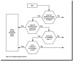
The explosion within the flameproof enclosure will impinge on the end of the cable where it emerges from the gland inside the enclosure. Exposure to repeated aggressive explosions can degrade the cable construction and lead to propagation along the cable through the gland and subsequent ignition of the surrounding flammable atmosphere. Barrier glands are designed to protect the end of the cable from explosion and are recommended where such a problem may arise. In other situations, flameproof com- pression glands can be used. The contributory factors are taken into account in the gland selection procedure shown in Fig. 15.3.
Motors with variable frequency supply
Traditionally it has been the responsibility of the user to ensure that the motor does not overheat as a result of misuse. This has been achieved through the use of devices such as current sensing protection relays. With converter supplies, the situation is
somewhat more complex and it is necessary for the motor manufacturer to assume the responsibility of rating the motor correctly for variable frequency inverter supplies.
These motors should be either type tested with the intended variable speed drive under the conditions of use or be equipped with internal temperature sensors which are arranged to disconnect the supply before the temperature class is exceeded. Thermistor sensors are usually mounted at critical points in the motor, and used to monitor motor temperature during operation. Trip relays are used to remove the supply from the motor if any one thermistor reaches the tripping temperature.
Conduit systems
Conduit should be either solid drawn or seam-welded heavy gauge steel. Specific types of flexible conduit may also be used. If the conduit is to be screwed directly into a flameproof enclosure, the thread should be of 6 g tolerance class and be long enough to allow five threads to be fully engaged in the enclosure wall. An explosion stopper is required on the enclosure wall or within 50 mm to prevent any explosion propagating along the conduit.
Increased safety equipment
Increased safety relies on a high standard of design and construction and the quality of the workmanship during installation is equally important. There is a great deal of detailed guidance in the manufacturers’ literature and BS EN 60097-14 summarizes the main features. The three critical areas are cable and conduit entries, wiring termi- nations and temperature limitation.
Cable and conduit entries
The primary objective of cable and conduit entry devices is to maintain the strength and IP rating of the enclosure. One way to achieve this is to use devices certified as increased safety and to use a sealing device, such as a washer, between the entry device and the enclosure. Certain types of standard industrial metal compression glands exceed the minimum requirements for increased safety and may be used instead of a certified equivalent. Where there is any doubt, and with non-metallic glands, a certi- fied device should always be used.
Wiring terminations
The majority of increased safety terminals fall into one of three basic design types, each with its own particular guidance for connection. Rail-mounted and so-called ‘chocolate block’ terminals comprise an insulating body through which a metal bar passes. Each end of the metal bar is recessed within the body and carries a wiring clamp. The wiring clamp may be a thin metal tongue which presses the wire onto the bar when the terminal screw is tightened, or it may be a saddle or yolk arrangement which is pulled up to the bar when the terminal screw is tightened and likewise presses the wire onto the bar. This type of terminal is designed for one wire at each end. A further type comprises a metal bar projecting from, or embedded in, the insulation of a component or part of an item of equipment. They are commonly found moulded into component parts of increased safety equipment, such as ballasts in luminaires. They have a wiring clamp in the shape of an inverted ‘U’ on top of the metal bar which is pressed onto the bar by a screw passing through both. These are designed to accommodate one or two conductors of the same or different sizes. A third common type of terminal is in the form of a threaded metal pillar with a vertical slot. A metal bar mounted inside a screw-on cap presses the conductors down on to the base of the slot. This design of terminal is intended to accommodate one or more conductors.
Conductors should preferably be fitted with compression ferrules before termination in any type of increased safety terminal, especially if they are stranded conductors or if the terminal is designed for more than one conductor. All strands of a conductor should be clamped securely and the conductor insulation should continue up to the metal part of the terminal.
Wiring within enclosures
The principal source of heat in a terminal box is the wiring. The temperature classification is based on the rated current of the terminals and is measured with wiring tails equal in length to the largest internal dimension of the enclosure. It is important that this length, the ratings of the terminals and the current rating of the conductors are not exceeded, or the temperature class may be exceeded.
Thermal protection of electrical machines
The thermal protection for increased safety of electrical machines is critical for two main reasons. The temperature in question is the hottest part of the interior, which may in a cage induction motor be the stator windings or the rotor bars. The temperature during starting and stalled operation is taken into account; on a fixed-frequency supply, the time taken to reach the limiting temperature of the temperature class, start- ing from the normal maximum running temperature, is marked on the rating plate. This is called the tE time and the protection must disconnect the motor within this time. Current-sensing protection with an inverse time delay characteristic may suffice if the motor run-up time is shorter than the tE time. Otherwise more sophisticated protection or embedded thermal sensors will be required.
Soft-start circuits and variable frequency/voltage drives need special attention.
Intrinsic safety equipment
Intrinsic safety is system-based and it has to be preserved throughout the entire installation. The two areas requiring particular care are wiring segregation and earthing. Intrinsically safe circuits need to be segregated from all other types of circuits and from each other. In the majority of intrinsically safe circuits only one connection to earth is acceptable. Guidance is given in BS EN 60079-14 in the following areas and should be consulted:
● location and installation of apparatus
● energy storage in cables
● cable types
● earthing of screens
● multiple earthing and electromagnetic compatibility
● cable armour bonding
● installation of cables and wiring
● marking/identification of cables, wiring and terminals
● multi-core cables
● unused cores in cables
● cable and wiring fault considerations
● design and justification of uncertified systems
● the use of uncertified ‘Simple Apparatus’
● temperature classification of wiring and cables
● cable entries
● installations in zone 0
Pressurized apparatus
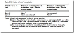
Pressurized apparatus is generally category 2, however it may be restricted to zone 2 applications depending on the action taken by the end-user on loss of pressurization. If the pressurized enclosure does not contain a source of release of flammable material the guidance shown in Table 15.12 should be followed.
If the enclosure contains a source of release of flammable material the documentation for the equipment should be consulted. Consideration of the following is required:
● any ‘Special Conditions’ of certification denoted by a suffix ‘X’ to the certificate number
● the nature of the containment of the flammable material
● the nature of the flammable material
● whether the supply of flammable material is shut off on loss of pressurization
● the nature of the equipment within the enclosure
● the external area classification
● whether the pressurizing medium is air or an inert gas
● whether the pressurization technique is ‘leakage compensation’ or ‘continuous dilution’
● the safety implications of sudden disconnection of the supply The enclosure will normally have to be purged with the pressurizing supply before the power can be turned on. The documentation supplied with the enclosure or the certification should be consulted to determine the purging flow rate and duration as these will be affected by any ducting connected to the enclosure during installation.
Type n equipment
Type n equipment comprises five subtypes which have been listed in Table 15.4.
In non-sparking apparatus (nA), the principles of design, construction and installation are similar to increased safety, so the same general guidance applies.
Notes: (a) parts with a source of ignition in normal operation.
(b) action should be taken to restore the pressurization as soon as practicable and within 24 hours in any case. Precautions should be taken to avoid the entry of a flammable atmosphere into the enclosure while the pressurization is off.
(c) if a more dangerous condition is created by sudden disconnection of the supply, a delayed switch-off may be justifiable or the reliability of the supply should be increased.
In restricted breathing enclosures (nR), the quality of the sealing is critical to the protection, so cable types and cable entries need careful specification and installation.
Energy-limited apparatus (nL) may be subgrouped like intrinsic safety and the same selection criteria apply. It may also be system-based rather than apparatus-based. If it is apparatus-based only the normal supply limits are relevant as the cabling is not energy limited. However, if it is system-based, the cabling will also be energy limited. This means that cable types, segregation, supply characteristics, energy storage in cables and earthing requirements are similar to those for intrinsic safety.
Simplified pressurization (nP) is similar to pressurization except there are relaxations on purging and action on loss of pressure. The general principles for pressurized instal- lations apply.
Type nC uses one of several protection techniques, which are enclosed break (similar to flameproof), sealing (using gaskets etc.), hermetic sealing (fusion sealed) and encapsulated. It may be subgrouped.
Personal electrical apparatus
Personnel may inadvertently carry personal electrical equipment such as electronic wrist watches, hearing aids, car remote locking devices, key-ring torches, calculators and so on into hazardous areas. The risk with wristwatches which have no other function such as a calculator is very small and generally acceptable. No other personal electrical equipment should be permitted in hazardous areas unless it is suitably protected.


