Motor and Generator Insulation Systems
Machine Insulation System
Insulation is obviously a limiting factor in the design of an electrical machine. If the thickness of the insulation is increased, the space available for the current carrying conductor is reduced and the conduction of heat from the conductor to the iron is restricted. Requirements of an insulation system for machine stator windings are
1. High dielectric strength
2. High resistance to partial discharges (PD)
3. High thermal conductivity
4. Good resistance to abrasions
5. Good resistance to tape separation caused by thermal heating
6. Good resistance to moisture and oil vapor
Machine insulation system is made up of five major insulation subsystems as discussed below.
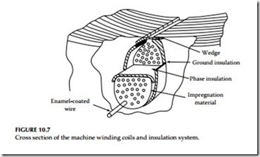
Turn-to-turn insulation system: Turn-to-turn insulation is located between separate wires in each coil. This is usually in the form of an enamel coating on the wire. Glass over enamel is used on severe applications both for formed and random-wound coils.
Phase-to-phase insulation system: Phase-to-phase insulation is located between adjacent coils in different phase groups.
Phase–to-ground insulation system: Phase-to-ground insulation is located between windings, as well as between windings and the ground or structural parts of the motor. A sheet material such as the liner used in stator slots provides both dielectric and mechanical protection.
Slot wedge insulation system: Slot wedge which holds conductors firmly in the slots is referred to as slot wedge insulation.
Impregnation insulation system: Impregnation is used to bind all of the other components together and to fill in the air spaces. A total impregnation applied in a fluid form and hardened, provides pro- tection against contaminants.
The various insulation systems that make up the machine insulation system are shown in Figure 10.7. Refer to Section 1.7 in Chapter 1 for additional information on insulating materials used for electrical equipment. The insulation systems used for machine windings are classified by NEMA and are listed below:
Class O: This insulation is rated for a total temperature of 100°C. It is made of materials or combinations of materials such as cotton, silk, and paper without impregnation.
Class A: This insulation is rated for a total temperature of 105°C. It is made of materials or combinations of materials such as cotton, silk, and paper when suitably impregnated or coated or when immersed in a dielectric liquid such as oil.
Class B: This insulation is rated for a total temperature of 130°C. It is made of materials or combinations of materials such as mica,
glass fiber, asbestos, etc., with suitable bonding substances capable of operation at 130°C.
Class F: This insulation is rated for a total temperature of 155°C. It is made of materials or combinations of materials such as mica, glass fiber, asbestos, etc., with suitable bonding substances capable of operation at 155°C.
Class H: This insulation is rated for a total temperature of 180°C. It is made of materials or combinations of materials such as silicone elastomer, mica, glass fiber, asbestos, etc., with suitable bonding sub- stances such as appropriate silicone resins and other materials capable of operation at 180°C.
Class C: This insulation is rated for a total temperature of 220°C. It is made of materials or combinations of materials such as Teflon and other natural or synthetic materials capable of operation at 220°C.
The industry standards, such as IEEE standards 112 and NEMA MG1 describe methods of temperature-rise measurements in rotating machinery. They are
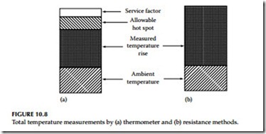
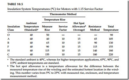
(1) measurements by thermometer and (2) resistance methods. Briefly, the resistance method is based upon the ambient and the total temperature rise, which is shown in Figure 10.8b. The thermometer method is based on four factors: (1) the standard ambient temperature of 40°C, (2) a service factor, (3) the measured temperature rise, and (4) the allowable hot spot. This is shown in Figure 10.8a. The various insulation systems normally used for machines are shown in Table 10.5.
The temperature determined by the resistance method gives an indication of the average total temperature of the motor windings. The life of the insulation system is dependent on both the temperature rise and the total temperature of the motor windings. The total temperature for the various insulation classes is shown in Table 10.5. The motor temperature measurement by resistance
method takes into consideration only two factors: the ambient temperature and the temperature rise measured by resistance at service-factor load. The sum of these two temperatures makes up the basis of total temperature of the insulation system. The resistance method eliminates the consideration of hot spot allowance, the 10°C allowance for service factor, and temperature rise measured by thermometer at nameplate load. Under the resistance method, the insulation system needed for the motor can simply be specified in terms of the operating ambient temperature and the service factor of the motor.
The use of the resistance method for the measurement of insulation temperature does not change the limitation imposed on the various classes of insulation systems. The resistance method has simplified the specification
b The hot spot allowance is a temperature allowance for the difference between the measured temperature rise of the winding and the estimated hottest location in the wind- ing. This number varies from 5°C to 25°C with measured rise, enclosure, and temperature measurement method.
of the insulation temperature rating system for machine windings. As a result of this change in the temperature measurement method, the class B insulation system has been adopted as a standard for motor windings.
Related posts:
Incoming search terms:
- materials used in class B of insulators
- insulation class used in electrical machines
- 3801-2047 class B 130°c transformer
- Which insulation class is us
- WHICH CLASS INSULATION IS USED IN ELECTRICAL MACHINES
- limited to class h generator insulation
- insulation i generator
- insulation generation classes
- insulation class h generator
- insulating materials used in motor and generator
- generator insulation
- generator coils require insulation between turns?
- generator class f insulation
- class of insulation
- class h insulation generator
- class 130 b converter model 3801-2047 product details
- winding temp standard


