Protective Relays
Protective relays are used in power systems to assure maximum continuity of service. They are constantly monitoring the power system to detect unwanted conditions that can cause damage to property and life. They can be consid- ered as a form of insurance designed to provide protection against property and personnel loss and as devices responsible for maintaining maximum possible continuity of service. Protective relays are found throughout small and large power systems from generation through transmission, distribution, and utilization. A better understanding of their application, operation, and maintenance is essential for the operating and maintenance personnel in order to understand how they fit into modern power systems.
Classification of Relays
ANSI C37.90 classifies relays associated with power apparatus into the following categories:
• Protective relays
• Auxiliary (slave) relays
• Programming relays
• Verification relays
• Monitoring relays
In addition to these generalized categories, protective relays can be further divided by input, operating principles, and performance characteristics. The input can consist of current, voltage, pressure, temperature, frequency, and so on; the operating principles can consist of thermal, electromagnetic, product of voltage and current, percentage, restraint, and so on; and the per- formance characteristics can consist of time delay, directional, differential, distance, phase or ground, comparison of operating quantities, and so on.
Overview of Protective Relays—Construction and Types
The evolution of protective relays from the perspective of construction and application can be described by four generations of relay designs. The four generations are categorized as following:
• Electromechanical and induction relays (first generation)
• Static relays (second generation)
• Solid-state relays with integrated circuits (third generation)
• Microprocessor relays (fourth generation)
The construction types of the above listed categories are discussed as follows:
9.3.2.1 Electromechanical and Induction Relays (First-Generation Relays)
Electromechanical and induction protective relays have lot of mechanical parts. These relays do not have the capabilities of autotesting of internal parts or providing an alarm in case a failure. The electromechanical and induction protective relay construction principles are based upon basic fault-detecting units, which are called basic relay units. The electromagnetic and induction relay chassis can be removed from the flexitest case for testing and maintenance purposes.
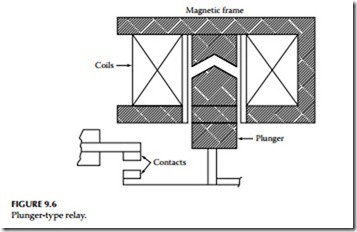
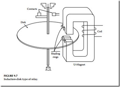
Most relays of this type used either electromagnetic attraction or electromag- netic induction principle for their operation. The electromagnetic, such as plunger type were instantaneous-type relays used for detecting overcurrent conditions. The induction-type relays provided overcurrent protection with time delays. Two or three input induction-type relays are used for directional or distance protection. Balanced-beam relays are used for differential protection, distance protection, or for overcurrent protection with low relay burden. For a general discussion, electromechanical relays can be classified into instantaneous (magnetic attraction) and time-delay (torque-controlled) units.
Instantaneous units
This type of relay unit consists of the plunger, solenoid, hinged armature, and balance beam types in which by magnetic attraction the armature is attracted into a coil or to a pole face of an electromagnet. Relays of this construction type can be applied in either AC or DC power systems. The plunger-type construction is shown in Figure 9.6.
Time-delay units
This type of induction-disk unit consists of the induction-disk or induction-cup type in which, owing to magnetic induction, a torque is produced in a movable rotor (i.e., disk or cup), which rotates between two pole faces of an
electromagnet. Obviously, this type of relay can only be applied in AC power systems. The induction-disk type of construction is shown in Figure 9.7. The preceding types of basic relay units are the electromagnetic type, however today these basic units can also be obtained in the solid-state (static) type.
Static Relays (Second-Generation Relays)
Static relays have been around for many years as far back as the early 1960s. These relays were also known as electronic or discrete solid-state relays. These relays used electronic components, such as unijunction transistors, thyristors, four layer diodes, and like components to provide protective func- tions similar to those provided by electromechanical relays. These relays were referred to as static relays because they employed discrete solid-state electronic components and had no moving elements or mechanical parts. Early versions of solid-state relays were very simple devices that typically provided a single function, such as voltage, current, frequency, or phase angle measurement similar to electromechanical relays. The static relays were built with eight groups of circuits broken into six functional categories. The function categories are: (1) amplifying, (2) interfacing or buffering,
(3) sensing or data processing, (4) timing, (5) annunciating, and (6) power supply. The static relays were usually mounted in a steel or steel and pheno- lic cases with draw out cradle. The relay unit (draw out cradle) is made of a steel frame which houses the motherboard, magnetics chassis and all of the electronic components used for the specific relay. The benefits of using solid- state components are that they are less affected by dirt, vibration, humidity,
and other environmental conditions. As the technology improved, solid-state relays began to include multiple functions, such as distance measurements and reclosing. The complexity of these devices also increased dramatically. Most of the static relays employ series shunt, or switch mode power supplies for their operation. Most static relays do not have the capability to detect failure of power supply and autotesting of internal parts, or provide an alarm in case a failure is detected.
Solid-Sate Relays (Third-Generation Relays)
These relays were introduced in the 1970s. These relays utilized integrated circuit boards and were more complex than the static relays. These relays performed many different functions for logic and control. As technology advanced, microprocessors were used to monitor certain conditions of the solid-state relay, such as power supply output voltages. As much of the logic was done in the microprocessor, these relays became smaller and more compact. In addition, they provided many more functions such as scheme selection, back up elements like time overcurrent elements, and control. The use of these relays was relatively short lived as digital relays became much more accepted. Solid-state relays came rack mounted, con- sisting of many printed circuit boards, as compared to electromagnetic and static types, which are permanently mounted on a switchboard. The solid state relay printed card can be removed from the case for testing and main- tenance purposes. For example, in the late 1960s, solid-state protection schemes were developed that required an entire 19 in. wide, 7 ft tall rack to contain all of the components and logic cards. The schemes were extremely fast and were primarily used on extra-high-voltage (EHV) circuits. These relays do not have the capability to detect failure of power supply and autotesting of internal parts, or provide an alarm in case a failure is detected similar to the second generation of solid-state relays.
Microprocessor Relays (Fourth-Generation Relays)
Microprocessor-based or digital relays were marketed in the 1980s. However, these relays did not incorporate the complex algorithms of today in the earlier designs of these relays for protection. Over time these relays began incorpo- rating multifunction protective functions that reduced the product and installation cost drastically. Today these relays include common hardware platforms, software platforms to perform many different functions and inte- grating protection with substation control. Although the basic protection principles have remained the same, the evolution of the digital relays using microprocessors has provided many benefits with a few shortcomings. Microprocessor relays are also referred to as numerical relays especially if they calculate the algorithms numerically. Digital relays are built using a microprocessor, an AC signal data acquisition system, memory components containing the relay algorithms, contact inputs to control the relay, and contact
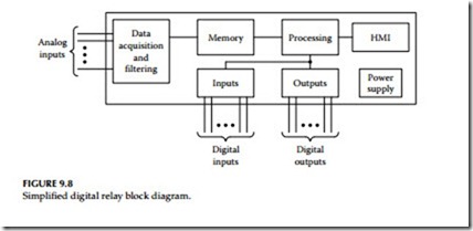
outputs to control other equipment. The algorithms and settings contained in the relay memory define the protection characteristics. Figure 9.8 shows a hardware block diagram for a typical digital relay design.
Analog values, currents and voltages are connected to the data acquisition and filtering block. Here the voltages and currents are reduced to low-level signals, typically ±5 V, so they can be converted to digital signals. Step-down instrument transformers provide isolation and from high voltage transients that may occur on the secondary wiring. The analog signals are filtered using a low-pass filter to remove high-frequency components and to prevent aliasing in the digital filtering process. The signals are then converted to digital values through an analog-to-digital (a/d) converter and multichannel multiplexer.
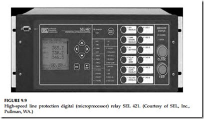
The output of the data acquisition block is mapped to memory areas. The data are stored for later use and are also passed to the processing block. The processing block reads and writes data to the memory block. This data is internal relay element status, digital input status, and digital output status. The processing unit also monitors the human machine interface (HMI), which typically consists of targeting light-emitting diodes (LEDs), pushbuttons, and a liquid crystal display (LCD). The power supply provides all of the control voltages that are required for operation of the electronic circuitry. Digital relays usually include automatic self-test func- tions. These self-tests verify correct operation of critical relay components. If a self-test detects an abnormal condition, the relay can close an output contact, send a message, or provide some other indication of the failure. The relay disables trip and control functions on detection of certain self- test failures. Since self-tests are executed often in the digital relay, they detect component failures soon after they occur. As a minimum, digital relay self-tests include tests of memory chips, a/d converter, power supply, and microprocessor. Figure 9.9 shows a high-speed line protection (SEL-421) digital relay manufactured by Schweitzer Engineering Laboratories, Incorporated (SEL).


