Electrical Switchgear Maintenance and Care
Switchgear components, such as circuit breakers, disconnect switches, fuses, and insulators, require regular inspection and maintenance. Switchgear can be of indoor or outdoor type and can be from different manufacturers. However, the maintenance of all types of switchgear can be carried out by following the basic maintenance operations. Also refer to Section 8.7.1, Chapter 8 on general guidelines for inspection of switchgear that may be used when inspecting medium voltage switchgear. This section provides the fundamental maintenance instructions for an overall maintenance program for switchgear. In cases where detailed instructions are required, the reader is advised to consult the recommendations of the manufacturer of the par- ticular equipment under consideration for maintenance.
MV Switchgear
Power Circuit Breakers
MV circuit breakers consist of air-magnetic circuit breakers either of hori- zontal drawout type or vertical lift type, oil circuit breakers, and vacuum circuit breakers. The following procedures should be carried out before new power circuit breakers are placed in service.
a. Receiving, handling, and storage
• Inspect the circuit breaker for damage that may have occurred in transit. Check the nameplate data and the packing list provided with the equipment delivered.
• Inspect the arc chutes of the air-magnetic breaker for cracks, damage, or foreign material.
• Inspect the shield on each of the fixed arcing contacts of the air-magnetic breaker for cracks.
• Lift and let down circuit breakers slowly. Do not use the bushing as handles when handling the breaker. Always roll and maneuver the breaker by grasping the top edge of the breaker cover. Avoid any sudden jerks when moving the breaker.
• If the breaker must be stored before it is put into service, keep it in a clean, dry, and noncorrosive place. Coat all bare metal surfaces with grease to prevent rusting or oxidation. If the breaker is to be installed outdoors, make sure power is available for space heaters and that they are working.
• In cases where a breaker is stored for a long period of time, it should be inspected regularly for rusting.
b. Installation
• Make an overall examination of the entire breaker to ensure that there are no damaged parts.
• Use a dry, clean cloth to remove dirt and moisture that might have collected on the circuit breaker.
• Cycle the breaker by opening and closing the breaker manually and electrically. Check for proper operation.
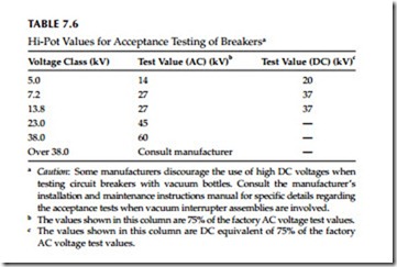
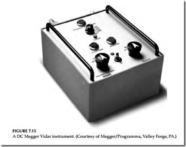
• To ensure that no damage has occurred during shipment, perform a high-potential (hi-pot) test on each breaker pole (or vacuum interrupter) while the breaker is in the open position. Test results should be evaluated on a go, no-go basis by slowly raising the test voltage to the values shown in Table 7.6. Hold the final test value for 1 min, if using an AC test method. If you are using a DC test method, you can operate the test using a Megger Vidar that takes only 5–10 s. If you do not get good results when testing a vaccum interrupter using the DC method, then first retest the vacuum bottle using reverse polarity. At that point, if the bottle fails again, then you will have to check it with an AC hi-pot instrument.
• Visually inspect the breaker before installation to make sure that all test jumpers or leads, specialized breaker tools or maintenance accessories have been removed before installing the breaker in its cubicle.
• Install the breaker into its cubicle in accordance with manufac- turer’s instructions. Check for proper operation by manually cycling the breaker with control power off. This should be done while the breaker is in the test or disconnected position.
Maintenance
Power circuit breakers, like other electrical equipment, require preventive maintenance to avoid equipment problems. The schedule for preventive maintenance can vary for each facility depending upon operating and envi- ronmental conditions. Frequent inspection and maintenance should be performed if the following factors are present:
• Corrosive atmosphere
• Excessive dust or dirt
• High ambient temperature and high humidity
• Older equipment
• Excessive repetitive duty
• Frequent fault interruption
Generally, the frequency of inspection should be based upon service and operating conditions. As a guide, inspect equipment about 6 months after it is installed and the follow up with scheduled maintenance every 1–3 years. In the performance of maintenance routines, all safety precautions should be followed.
Preventive maintenance should include the following areas:
1. Circuit breaker
a. Contacts
b. Arc chutes
c. Mechanical parts
d. Auxiliary equipment
2. Cell enclosure
a. Cell joints (i.e., bus joints)
b. Cell contacts
c. Insulation
The following routine maintenance instructions are offered as a general guide for the maintenance of power circuit breakers. If special detailed instructions are required, consult the manufacturer.
Air-Magnetic Circuit Breakers
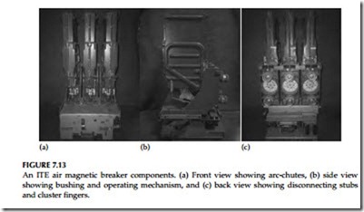
Before inspecting or performing any maintenance on either the breaker or its mechanism, be sure the breaker is in the open position, is disconnected from all electrical sources, and is removed from the cubicle (Figure 7.13a, b, and c). Both the closing and opening, springs should be discharged or blocked mechanically before any maintenance is done. The old air magnetic breakers, in many cases have been retrofitted (replaced) with vacuum breakers in the same switchgear. The vacuum breaker retrofit is a direct one-for-one replace- ment without involving any other equipment conversions. For maintenance of vacuum breakers in retrofit applications, refer to Section 7.3.4 for guide- lines and instructions on vacuum breakers.
1. Record the number of operations and perform a general visual inspection of the breaker. Report any unusual signs of problems.
2. Put circuit breaker in test position and, using a test coupler, operate breaker electrically. Check the operation of all electrical relays, sole- noid switches, motors, control switches, and indicating devices.
3. Remove circuit breaker from enclosure and perform visual inspection as follows:
a. Remove box barriers.
b. Wipe clean of smoke deposit and dust from all insulating parts, including the bushings and the inside of the box barrier. Use a clean, dry, lint-free cloth; a vacuum cleaner would be helpful.
c. Inspect the condition of bushing primary disconnect stubs and finger cluster.
d. Inspect the condition of bushing insulation; it should be clean, dry, smooth, hard, and unmarred.
e. Check breaker and operating mechanism carefully for loose nuts, bolts, or retaining rings, and ensure that mechanical link- age is secure.
f. Inspect insulation and outside of arc chutes for holes or breaks; small cracks are normal.
g. Inspect magnetic blowout coils (if used) for damage.
h. Inspect all current-carrying parts for evidence of overheating.
Functional inspection
• Sand throat area of arc chutes with garnet paper or other noncon- ductive, abrasive paper until thoroughly clean.
• Ensure that arc chutes are clear of contamination and have no sig- nificant damage on grids or ceramics. If ceramics or fins are broken, replace arc chutes.
• Ensure that all brazed, soldered, or bolted electrical connections are tight.
• Inspect contacts of control relays for wear and clean as necessary.
• Check actuator relays, charging motor, and secondary disconnects for damage, evidence of overheating, or insulation breakdown.
• Check that all wiring connections are tight and for any possible damage to the insulation.
• Replace any wire that has worn insulation.
• On stored-energy breakers, operate the breaker slowly. By using the spring blocking device, check for binding or friction and correct if necessary. Make sure contacts can be opened or closed fully.
• Inspect the arcing contacts for uneven wear or damage. Replace badly worn contacts. Measure the arcing contact wire, using an ohm- meter. Make adjustment if necessary. Refer to the appropriate instruc- tion book.
• Inspect primary contacts for burns or pitting. Wipe contacts with clean cloth. Replace badly burned or pitted contacts. Rough or galled contacts should be smoothed with a crocus cloth or file lightly. Resilver where necessary.
• Inspect primary disconnect studs for arcing or burning. Clean and lightly grease arcing contacts.
• Check primary contact gap and wipe. Make adjustment as per appro- priate instruction book. Grease contacts with an approved grease and operate breaker several times.
• Check operation and clearance of trip armature travel and release latch as per appropriate instruction book. Replace worn parts.
• Inspect all bearings, cams, rollers, latches, and buffer blocks for wear.
Teflon-coated sleeve bearings do not require lubrication. All other
sleeve bearings, rollers, and needle bearings should be lubricated with
SAE 20 or 30 machine oil. All ground surfaces coated with dark molyb-
denum disulfide do not require lubrication. Lubricate all other ground
surfaces such as latches, rollers, or props with an approved grease.
• Install box barriers.
• Measure insulation resistance of each bushing terminal to ground and phase to phase. Record readings along with temperature and humidity.
• Perform hi-pot test for breaker bushing insulation (optional).
• Check closed breaker contact resistance (optional).
• Perform power factor test (optional).
• Perform corona test (optional).
• Using test box, operate breaker both electrically and manually. Check all interlocks.
• Insert and operate breaker in cabinet. Watch for proper operation of the positive interlock trip-free mechanism. (Breaker should trip if not fully in or in test position.)
• Remove breaker from cubicle and check primary disconnect wipe; refer to appropriate instruction book.
• Perform visual inspection and check for proper operation as dis- cussed under Section 7.3.1.1.b before inserting breaker into cubicle ready for energization.
Oil Circuit Breaker
The oil circuit breaker should be maintained on a periodic basis similar to the air-magnetic circuit breakers. To maintain the circuit breaker, mount it on the inspection rack and untank it to expose the internal parts. Check for the follow- ing and make adjustments and repairs in accordance with the instruction book.
• Wipe clean all parts, including any carbon markings. Insulating parts should be inspected for damage such as warp age and cracks; replace damaged parts.
• Inspect the contacts for alignment and wear. Replace pitted and burned contacts and file rough contacts. Adjust contacts to ensure that contacts bear with firm and even pressure.
• Take an oil sample and make a dielectric test as explained in Chapter 4 under testing of insulating liquids. If visible carbon particles are evident in the oil, filter oil regardless of the dielectric strength.
• Wipe inside of tank, barriers, and tank linings to remove carbon.
• Inspect and clean operating mechanism similar to that described in Section 7.3.2.
• Check the breaker operation by slowly closing with the closing device similar to the air-magnetic breaker. Also check its electrical operation.
• Replace tank with proper oil level and make sure that all gaskets, tank nuts, and flange nuts are tightened properly to prevent leakage.
Vacuum Circuit Breaker
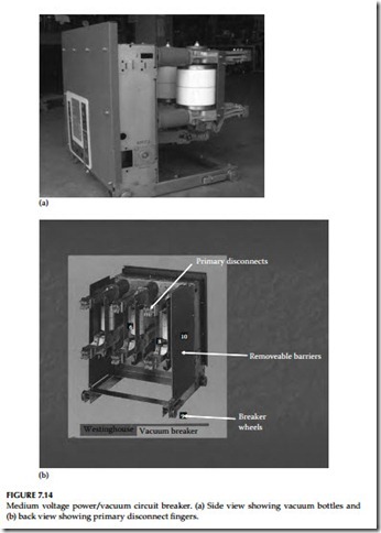
The vacuum circuit breaker (Figure 7.14a and b) maintenance schedule should be based upon operating experience and environmental conditions. If such a schedule has not been determined, it is recommended that the breaker be inspected at least once a year or every 2000 operations, whichever occurs earlier. However, a breaker should be inspected every time after a severe fault interruption. The following checks should be performed for the vacuum circuit breaker:
• Check for contact erosion. To determine contact erosion, remove breaker from enclosure. Close the breaker and measure the spring plate overtravel. Consult the manufacturer’s instruction book for allowable overtravel. If the specified overtravel is exceeded, the vacuum interrupter must be replaced.
• To check the condition of the vacuum, perform a hi-pot rest. Consult the manufacturer’s instruction book for test value or use 60% of the final factory test value.
• Using a clean, dry cloth remove all dirt and moisture from the outside of vacuum interrupters and all insulating parts.
• Check the entire operating mechanism similar to the air-magnetic circuit breaker.
• Lubricate ground surfaces such as cams, gear teeth, rollers, and pawls when performing maintenance. See the manufacturer’s guide on lubrication methods and time periods.
• Operate the breaker manually and electrically several times to make sure that the breaker is operating properly.
Electrical tests of the vacuum bottle integrity can be performed using either an AC or DC method. Also, vacuum bottle integrity can be checked using a DC Megger Vidar Instrument. The test using a Vidar only takes 5–10 s. A Megger Vidar instrument is shown in Figure 7.15.
Switchgear Enclosure and Bus
An inspection of the switchgear bus and enclosure should be made every year. However, inspection frequency can be increased or decreased depending on operating and environmental conditions. It is good practice to follow the
manufacturer’s recommendations regarding maintenance procedures. The fol- lowing are suggestions to supplement the manufacturer’s recommendations:
• Check the enclosure housing to ensure that all hardware is in place and in good condition. The purpose of enclosure is to protect the equipment from outside contaminants and prevent exposure of per- sonnel to live parts. A maintenance program should assure that these features are maintained. Lubricate hinges, locks, latches, and so on.
• For outdoor assemblies, check for roof or wall leaks, as well as for damage from previous leaks.
• After the power has been turned off and the bus has been grounded, remove dust and dirt by wiping with a dry, clean cloth or by vacuuming.
• Check for all unnecessary floor openings and any water pools at the base of enclosures. Seal such openings with duct seal. Check for signs of moisture accumulation, such as droplet depression on dust- laden surfaces and dust patterns. Prevent moisture accumulation by providing heat and ventilation. Therefore, make sure that space heat- ers and fans are functioning properly.
• Check that ventilators are clear of obstruction and air filters are clean and in good condition.
• The surface of all insulating members should be inspected before any cleaning or dusting, as well as after cleaning for signs of electrical
distress, tracking, corona, and thermal heating. Damage caused by electrical distress will usually be evident on the insulating surface as corona markings or tracking parts. The areas most susceptible to electrical distress are
a. Splices and junction points
b. Boundaries between adjoining insulators
c. Edges of insulation surrounding mounting hardware grounded to the metal structure
d. Bridging paths across insulating surface
e. Boundaries between an insulating member and the grounded metal surface
f. Hidden surfaces such as adjacent edges between upper and lower members of split bus supports
g. Sharp edges in switchgear that are not insulated
• Check for loose bolted connections in bus bars, splices, and the like, for signs of heating. Tighten in accordance with manufacturer’s recommendations.
• Examine grounding connections and ground bus for tightness and cleanliness.
• Check alignment and contacts of primary disconnecting devices for abnormal wear or damage. Check for sulfide deposits and use a solvent such as alcohol for removal of these deposits.
• Remove any paint damage or finishes.
• After cleaning and adjusting, run an insulation resistance test to measure resistance to ground. Compare the values of test readings with previous readings for any sign of weakening of the insulation system. Readings should be normalized to a common temperature and humidity base before comparison is made.
• Compare equipment nameplate information with latest one-line diagram and report discrepancies.
• Check tightness of accessible bolted bus joints by calibrated wrench method. Refer to manufacturer recommendations for proper torque values.
• Test key interlock systems physically to ensure the following:
a. Closure attempt should be made on locked-open devices
b. Opening attempt should be made on locked-closed devices
c. Key exchange should be made with devices operated in off- normal positions
• Check for cracks in extruded red sleeving bus insulation made from Lexan or Noryl. Repair cracked insulation according to manufacturer’s recommendations.


