MARINE CURRENT ENERGY
Marine current converters, sometimes also called tidal stream converters, utilize the energy contained in flowing water generated by the motion of the world’s tides as a source of electrical power. Currents of this type can be found in many estuaries around the world and also in coastal straights and areas where there are offshore coastal features that allow the tidal movement to create a significant current. In principle, the same type of converter can be used in a river, too, as an alternative to a conventional hydropower plant.
The amount of energy that is available in a marine current depends on both the amount of water that is moving and the speed at which it flows. Areas where there is a large tidal reach are likely to offer the best marine current potential since the volume of water moving on each tide will be large. Meanwhile, the faster that water flows, the greater the energy it contains.
The energy that flowing water contains varies as the third power of its velocity so energy content is extremely sensitive to speed. A site with a fast current will therefore offer the most efficient way of harnessing this source of energy. Such sites may be found where the natural flow is constricted either in a river or offshore. Average flow rates of 2 m/s or more are generally considered ideal for a marine current power plant.
While some marine current plants may take energy from flowing river water, most will exploit tidal motion. The latter is both cyclical and variable, with the strength of the current depending on the state of the tide. This needs to be taken into account when designing a marine current project. There will be a small seasonal change too as the tides vary between spring and neap tides (the two extremes when the gravitational pulls of the moon and the sun either reinforce or oppose one another). The flow in river sites, on the other hand, will have little short-term variability but may vary significantly from summer to winter.
Flowing water is conceptually similar to flowing air. In consequence, the most common methods of extracting energy are similar to those developed for wind power—that is, turbines with several blades that rotate in the flow. However, because water is much denser than air, the energy density of flowing water is much greater so turbines can be much smaller for the same power out- put. For example, a 10 m diameter turbine in water flowing at 4 m/s can gen- erate around 880 kW, whereas a 10 m wind turbine turning in a wind speed of 4 m/s would barely achieve 0.5 kW. For a similar output, the wind turbine would need to have a diameter of around 70 m.
In a 2 m/s flow of water an 18 m diameter turbine is needed to sweep out (or intersect) water carrying a power density of 1 MW. At 4 m/s the turbine size needed to sweep out a power density of 1 MW falls to 6 m. Only around one-third of the energy swept out is captured and converted into electricity, so for a 4 m/s flow a 1 MW marine generator would need to be a little more than 10 m in diameter.
Marine Current Energy Converters
Based on the analogy with moving air, most marine current converters are turbines that rotate in the water flow, providing a mechanical power output that can be converted into electricity. Many exploit technology similar to that used by the wind industry. The conventional wind turbine in use today is a horizontal- axis wind turbine mounted on the top of a tall tower. Exactly the same type of technology can be used for marine currents with, in this case, the tower fixed to the sea or riverbed.
It is possible to carry this analogy too far and there are often significant dif- ferences between wind and water turbines, particularly concerning the means of mounting the latter in the water flow. While all wind turbines are placed on towers, marine current turbines can be mounted on towers, they can be hung from the bottom of floating supports, and they can be mounted on buoyant structures that are anchored to the seabed or riverbed. Generators may vary too with some marine devices using rim generators that allow greater flow through the turbine.
There is also a viable alternative to the horizontal-axis wind turbine for marine power: the vertical-axis turbine. Various forms of the latter were tested during the early days of wind power development, but as the technology matured the designs were mostly abandoned for the standard design in use today. The vertical-axis turbine has several significant advantages for marine current deployment. The most important of these is the ability to continue to rotate in the same direction, whichever way the current flows. The vertical shaft of the turbine, meanwhile, allows the generator to be mounted at one end. This might either be at the surface if the turbine is deployed from a floating barge, or on the seabed.
Another way of extracting power from a tidal flow is with a paddled wheel, conceptually identical to the old mill wheel used to drive water mills. Such wheels or turbines are only partly submerged, with water flowing against the submerged part of each paddle. Technically, this is known as a cross-flow tur- bine. Such devices are being used today but they are generally not as efficient as fully submerged turbines. However, the technology is simple, which may be advantageous for small installations. (There are fully submerged versions of cross-flow turbines available too.)
There are a number of other means of extracting power from flowing water. These include oscillating airfoils that rise and fall in the flow, with the oscillating movement used to drive a pump or generator, and devices based on the Venturi effect when water is constricted to flow through a narrow passage.
Horizontal-axis Turbines
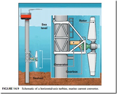
A horizontal-axis marine turbine will often share many features with a similar wind turbine. A typical device may have a three-bladed rotor mounted on a shaft that drives a generator through a gearbox. Since it will be operating under water, all the electrical and mechanical components must be protected in a watertight container. Gearboxes have been notorious as a point of weakness in wind tur- bines and designers have developed direct-drive systems that eliminate them. Similar systems can be applied to marine turbines. Variable-speed generators have also been deployed in the wind industry, with electronic AC-DC-AC converters to match the output to grid frequency. Again these are becoming common within the marine industry. See Figure 14.9 for a schematic of a horizontal-axis turbine.
While many tidal stream turbines have three blades some may have two and others more. These may be of a fixed pitch, which is structurally the simplest design, or they may be capable of varying the pitch to control rotational speed. Speed control is generally less critical for tidal stream turbines since the water speeds are much more predictable than wind speeds. In addition, whereas wind turbines require the ability to be shut down in high winds, this facility is not needed in a marine turbine since such extremes do not generally exist (although exceptionally, they might be encountered on a flooded river).
Many marine turbines will have open blades but some designs include a shroud that encloses the blades. This shroud can serve two purposes: to protect the blades from damage and prevent marine animals from being damaged by the blades, and to control the water flow.
A shroud can make the turbine more efficient in a cross-flowing current, which is likely to be common in the marine environment where current directions change with the tide. A correctly designed shroud can also improve efficiency by acting as a diffuser that flares on the downstream side of the turbine. This serves to increase the flow through the turbine and can increase efficiency from 35% for an open turbine to 60% for a well-designed shrouded design.
Marine turbines with shrouds lend themselves to an unconventional type of generator design called a rim generator. In this type of machine the generator rotor has no central shaft but is instead mounted on the blade tips of the rotor that penetrate into the surrounding shroud. The rotor itself forms a part of the generator. The generator stator, meanwhile, is built into the shroud. Such a design has only one moving part—the rotor—and since there is no axially mounted generator, there is less impediment to flow through the rotor, leading to higher efficiency. However, the technology is less well tested than conventional generator design and remains to be proven.
There are several means of mounting horizontal-axis wind turbines in the water flow. The simplest, conceptually, is a monopole tower that is sunk into the seabed or riverbed with the turbine mounted on top of it. However, these can be expensive to install. An alternative is a gravity foundation that holds itself in position by means of its mass.
Buoyancy can be utilized too. One approach is to make the turbine structure buoyant and anchor it to the seabed. Such tethering systems are not as stable as a monopole but they are much cheaper. Turbines can also be hung from floating platforms.
Ease of maintenance is always an issue in a marine environment. Since maintenance cannot be carried out with ease under water, a means must be provided to raise the turbine out of the water. Some monopole structures are telescopic and can be raised to bring the turbine to the surface. In other cases, the monopole extends above sea level and the turbine can be raised and lowered on it. Buoyant turbines anchored to the seabed can be raised by untethering them, while those on floating platforms can be raised onto the platform for maintenance to be carried out.
All marine mounting systems are expensive and it is often cost effective to mount two or more turbines on a single support. They are often mounted in pairs, with each member of the pair rotating in the opposite direction to the other to balance the rotational forces about the mount.
Vertical-axis Turbines
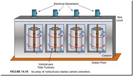
A vertical-axis turbine has its blades mounted onto a vertical shaft (Figure 14.10). The vertical-axis design has two significant advantages: it will rotate whatever direction the water flows, and its generator can be mounted at the top or bottom of the shaft.
The insensitivity to flow direction means that a vertical-axis turbine will oper- ate efficiently in a tidal region where the flow reverses twice a day. It will also be unaffected by cross-flows that might reduce the efficiency of a horizontal-axis tur- bine. Depending on the site this could prove a great advantage. Meanwhile, the ability to mount the generator at either end of the shaft means that it can be placed either on the seabed or riverbed or, more usefully, it can be deployed above sea level either from a shaft extending beyond the sea or on a floating support.
Vertical-axis turbines can come in a variety of shapes. One of the most pop- ular from the early days of wind turbine development is the Darrieus or egg- beater design, so-called because its curved and twisted blades resemble the kitchen implement. Others have vertical blades mounted onto the shaft using horizontal struts to create an H-shaped rotor.
The H-shaped rotor has an additional advantage—it sweeps out a rectangular area as opposed to the circular sweep of a horizontal-axis turbine. This means the dimensions of the rotor can be tailored to the shape of the

